
1990s Millport CNC Vertical Mill Revival
[06.12.24]
There comes a point in every man's life when he simply cannot say no. Sometimes it's over a car or a house loan. Sometimes it's helping a friend move. Sometimes it's over a romantic relationship. Other times its the opportunity to pick up free machining equipment. I'm not talking about wood shop tools or a little scroll saw, I'm talking about properly huge, big-boy Bridgeports and CNC equipment. Equipment that overflows 2ft square wooden shipping pallets. One warm June day my brother, Thomas, got that call. He put everything down, grabbed a trailer and picked up a very 1990s CNC machine along with a slew of cutters, lathe chucks and tooling in need of a new home. That and a very incomplete wire EDM, but that's a story for another day.
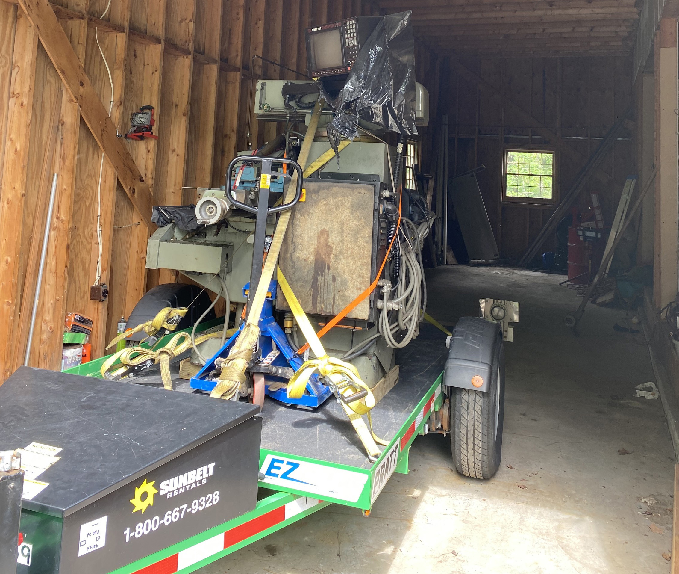
Drop deck trailers are both a blessing and a curse. You see, they let you move heavy items with ease, but lose floor space in a breeze! Being the family iron aficionado, Thomas has collected his fair share of production machinery and cast iron americana - more so than the entire male <50yr age bracket on the east coast. Thus, drop deck trailers have contributed more to the displacement of earth's rotational inertia than any natural geothermal or galactic event in the past 50 years.
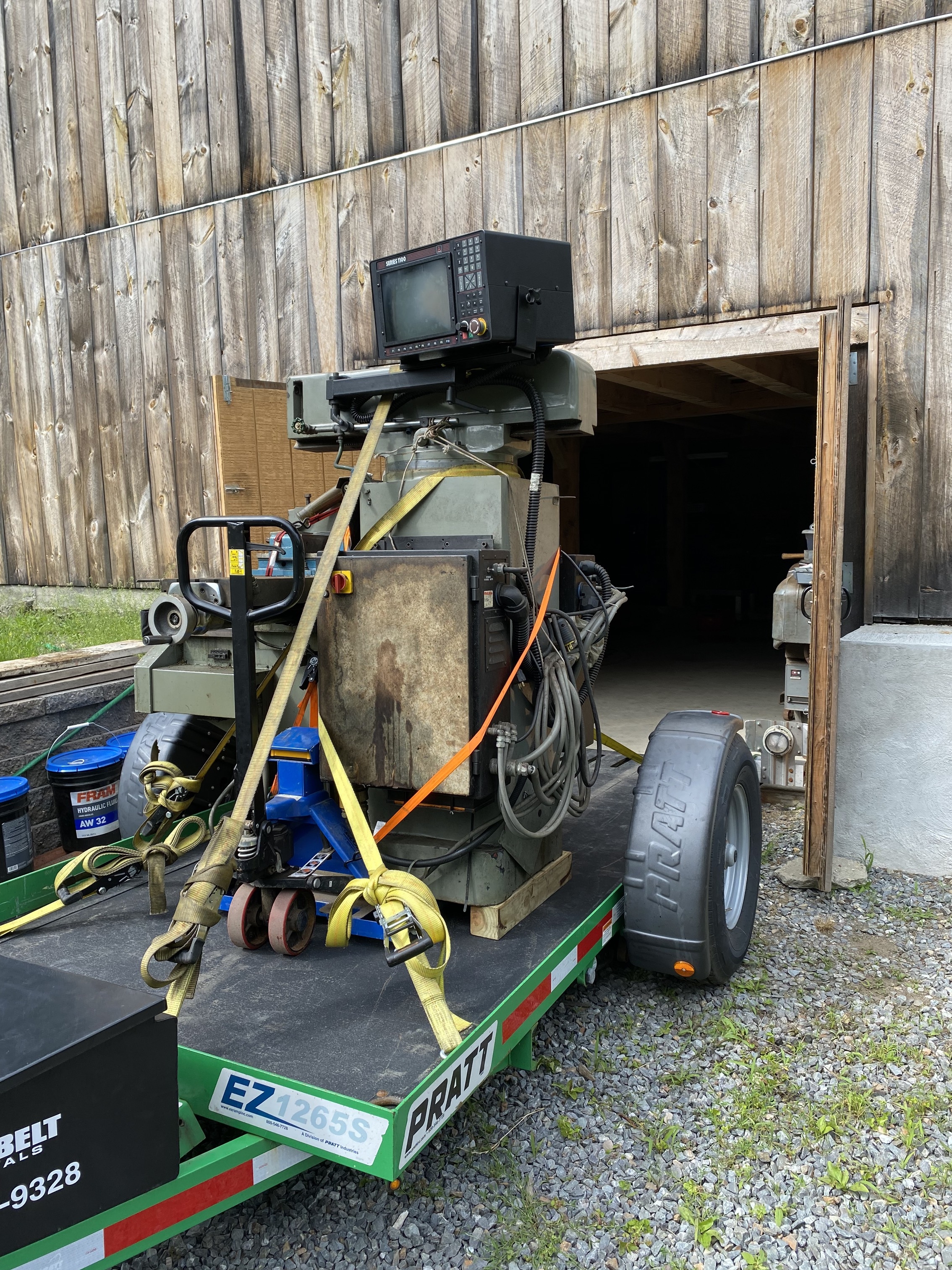
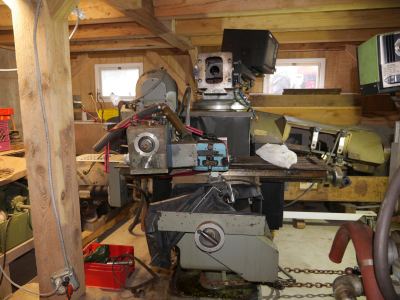
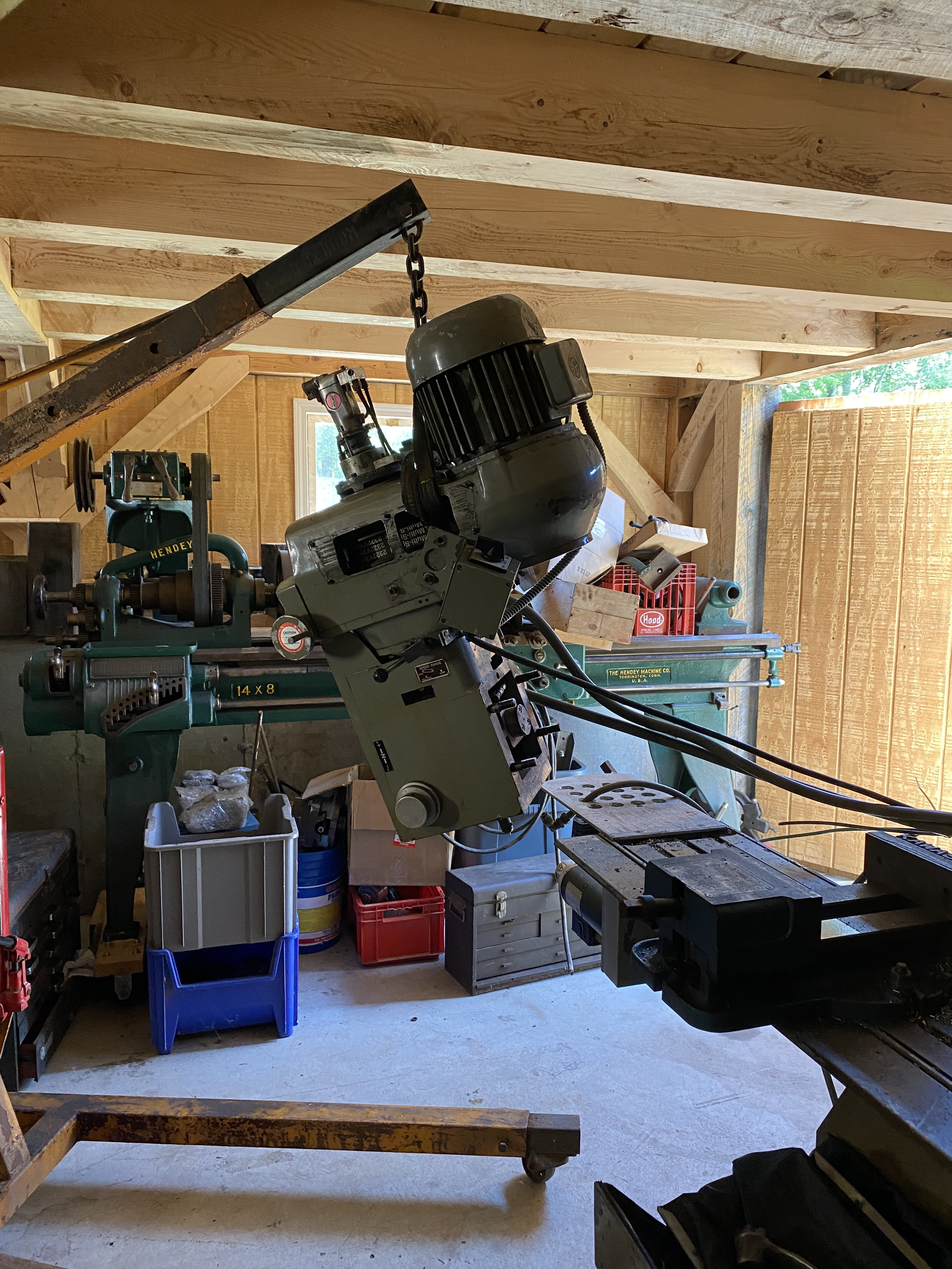
The major hurdle of the great move was a z-height over limit condition. Yes, the Z-axis assembly was too tall to pass through the bottom barn doors, and even the door trim removal was not enough to compensate for the chunky Z-axis head assembly. Zip it off and continue? Not so fast speed-racer, it weight upwards of 500lbs! An engine crane was of great assistance for the removal but the re-installation was a quite a logistical workout. An engine crane is great for moving large items without positional accuracy. The Z-axis needs to be aligned and planar for the CNC to work properly. The crane was not going to be enough. Thomas came up with a clever plan, he used the engine crane to install the z-axis head vertically into the vise, torqued it down, then used the table/knee to align the bolt pattern to the ram. Using the machine itself for alignment is pure excellence and only worked because the shear mass of the machine is enormous and the 500+lbs on the table was no sweat.
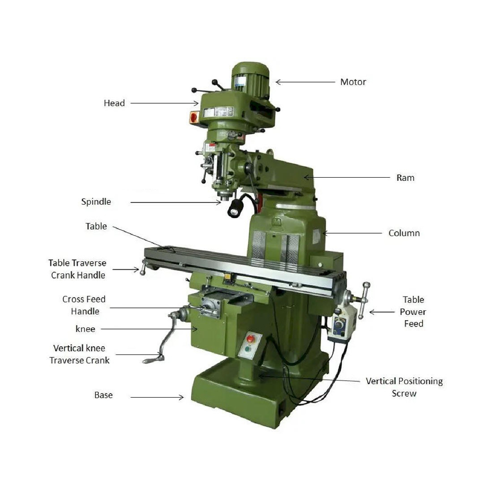
In case anyone needs a refresher, here is the XYZ coordinate system traditionally used for CNC equipment. All axis are labeled:
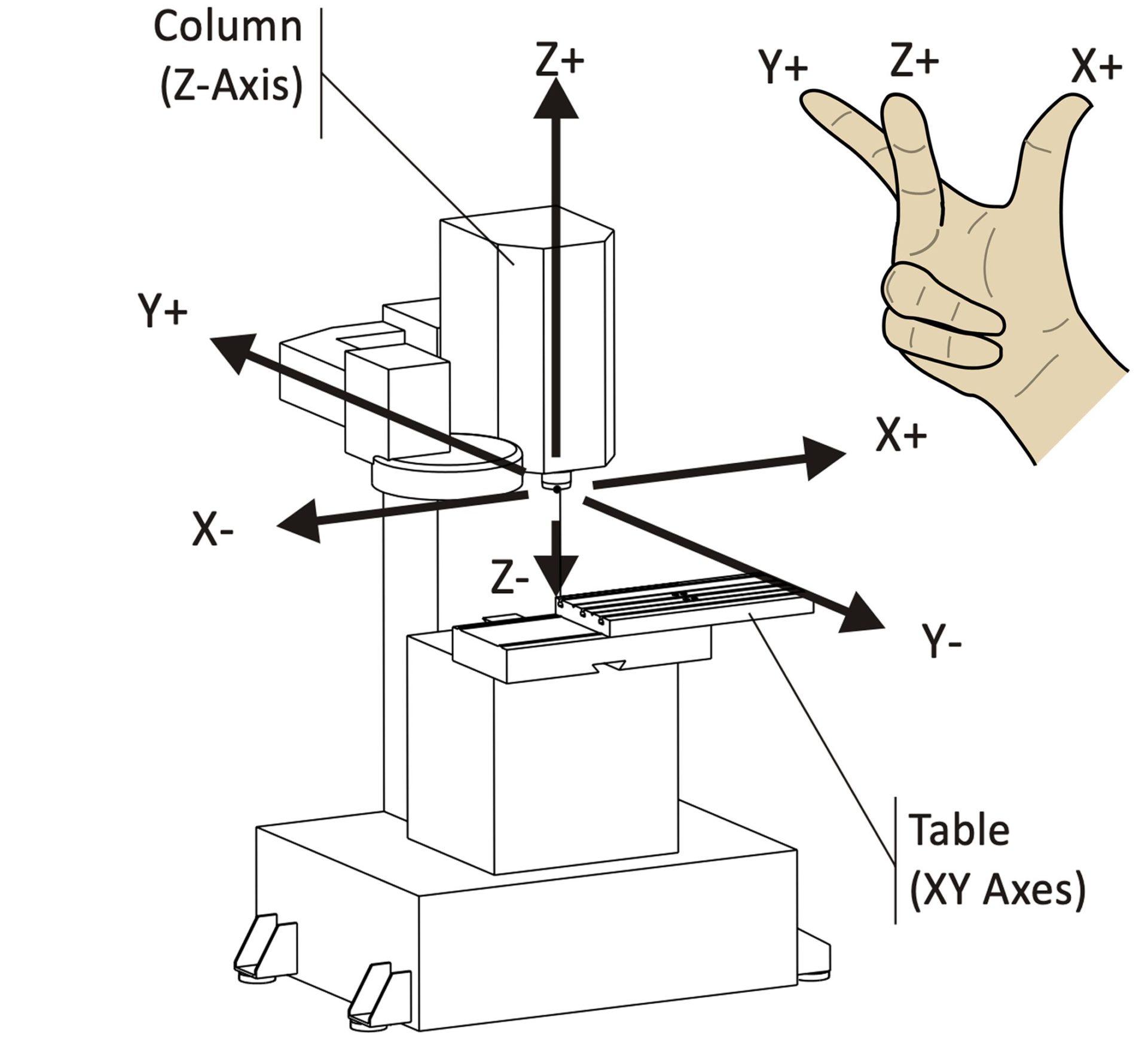
XYZ Coordinate System. Credit: Autodesk
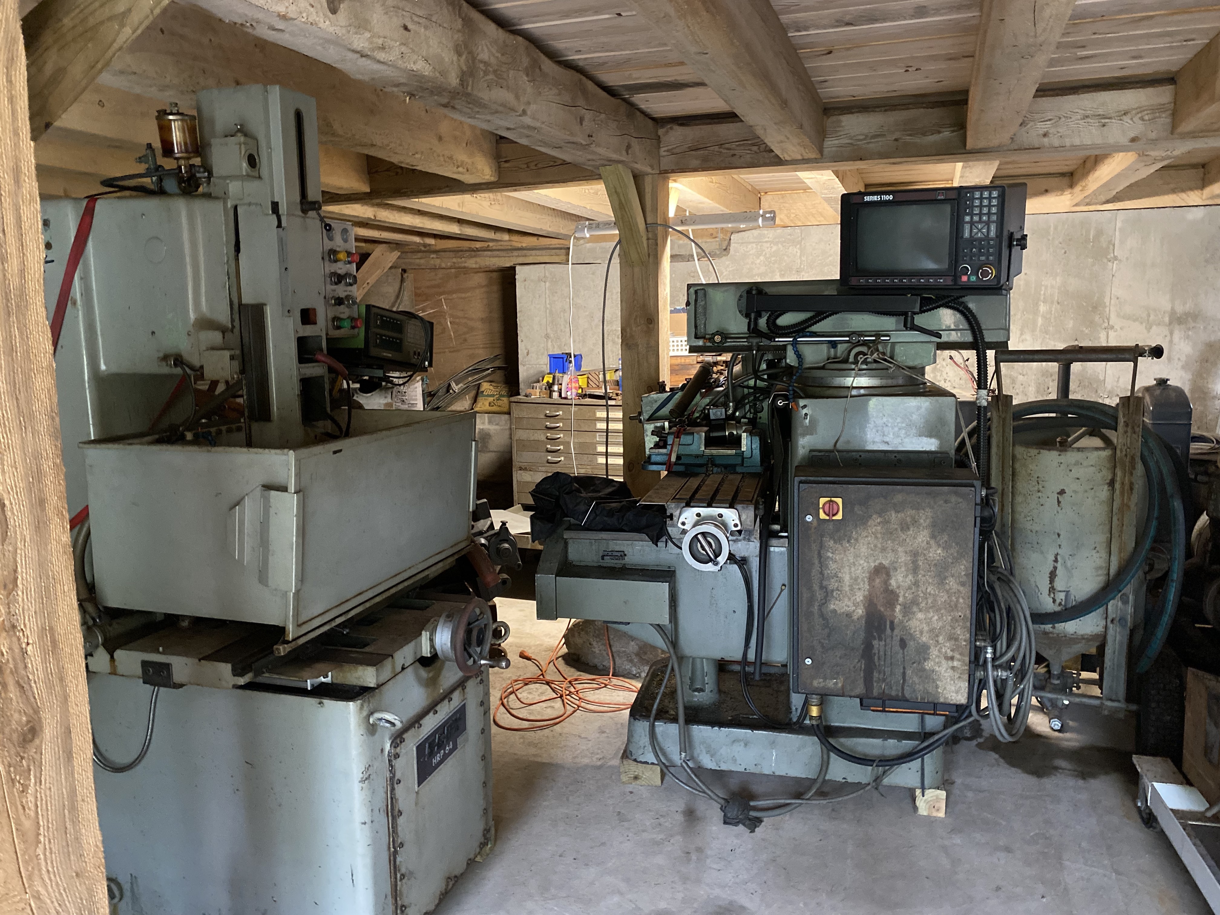
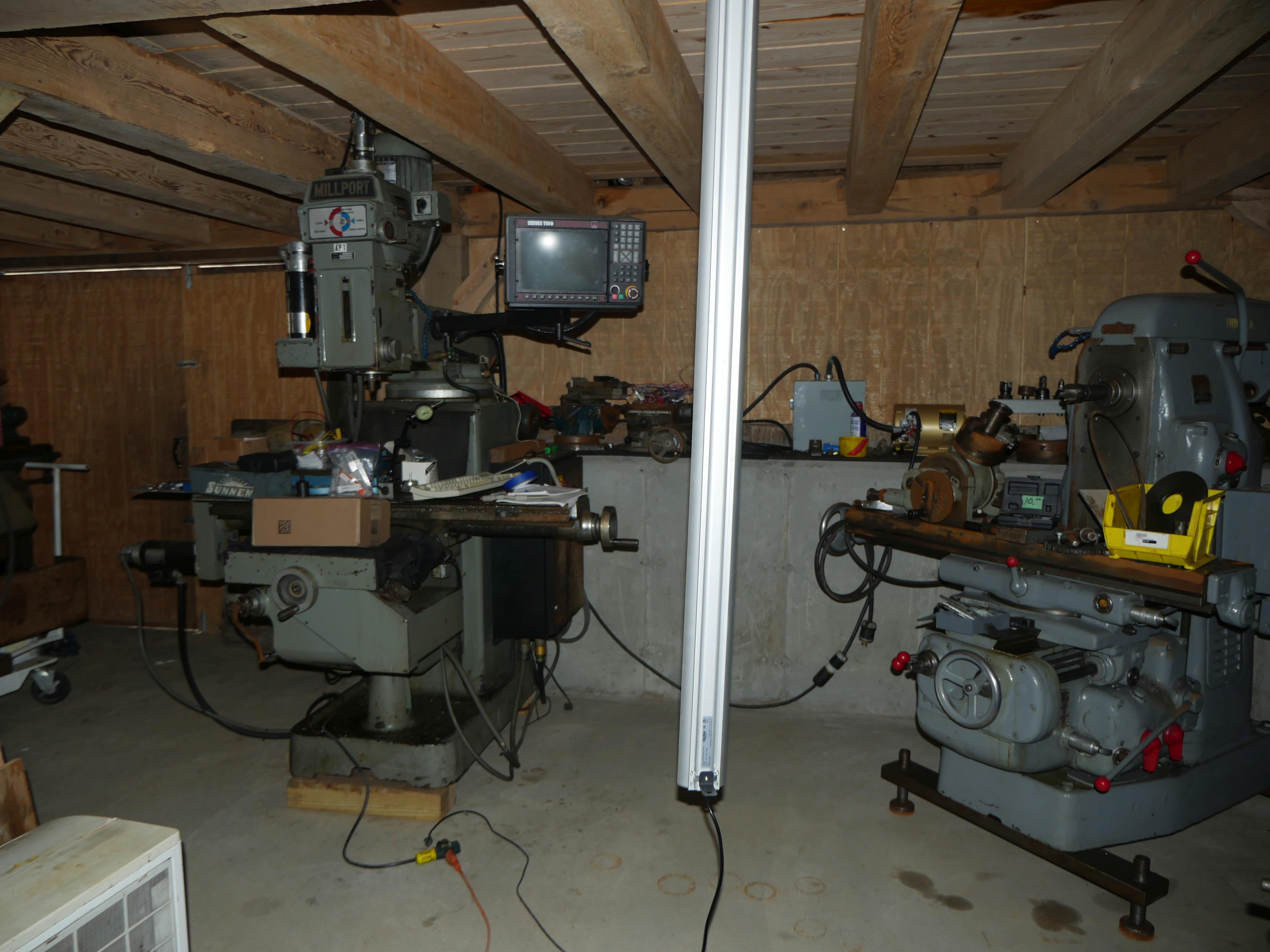
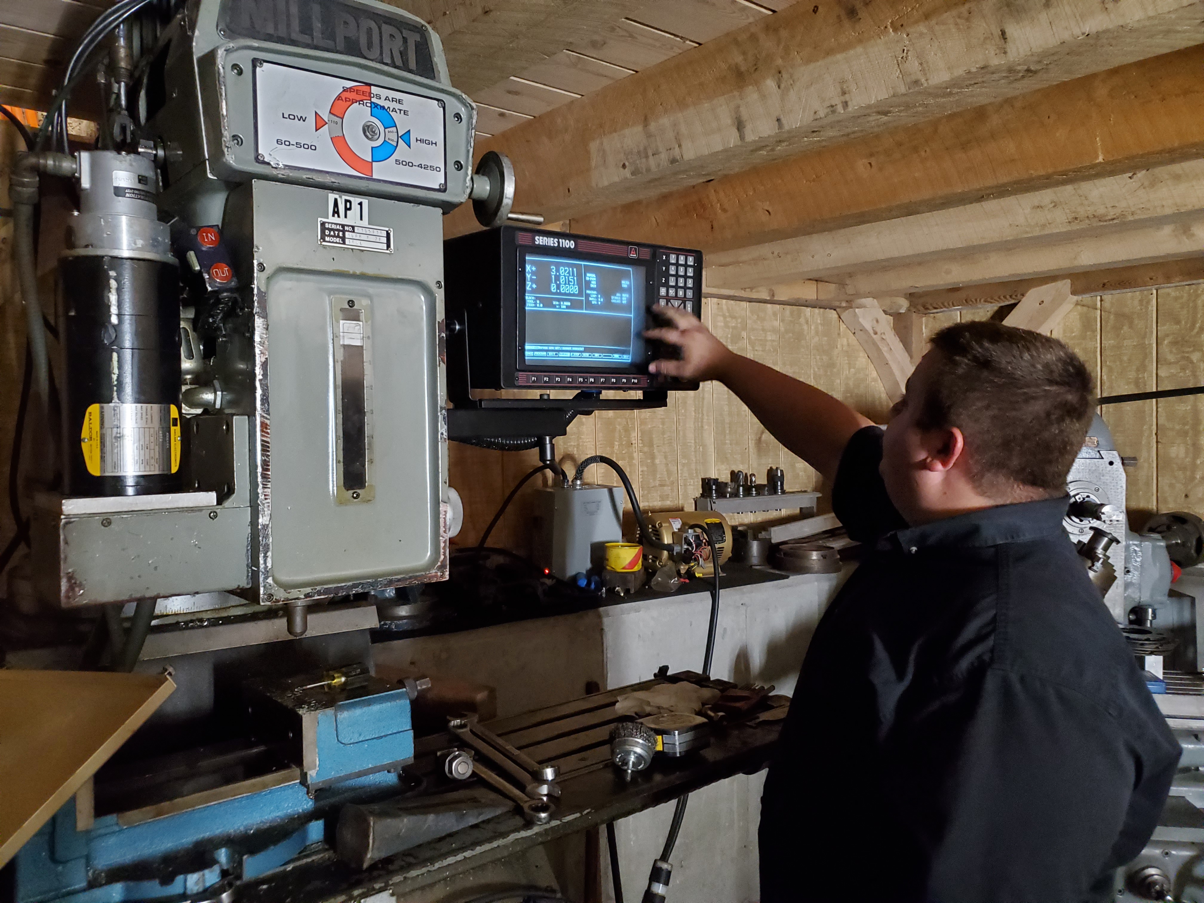
After final positioning and leveling, I was finally able to investigate the dusty and unknown automated clone Bridgeport that was now cluttering Thomas' lower workshop. Computer Numerical Control represented a large stepping stone for automated production from the 1970s-today, with controlled XYZ axis setting the stage for repeated task automation. Increased computational power per square inch (Moore's Law) resulted in a step function boost in efficiency to a plethora of industries, and the manufacturing industry was no exception.
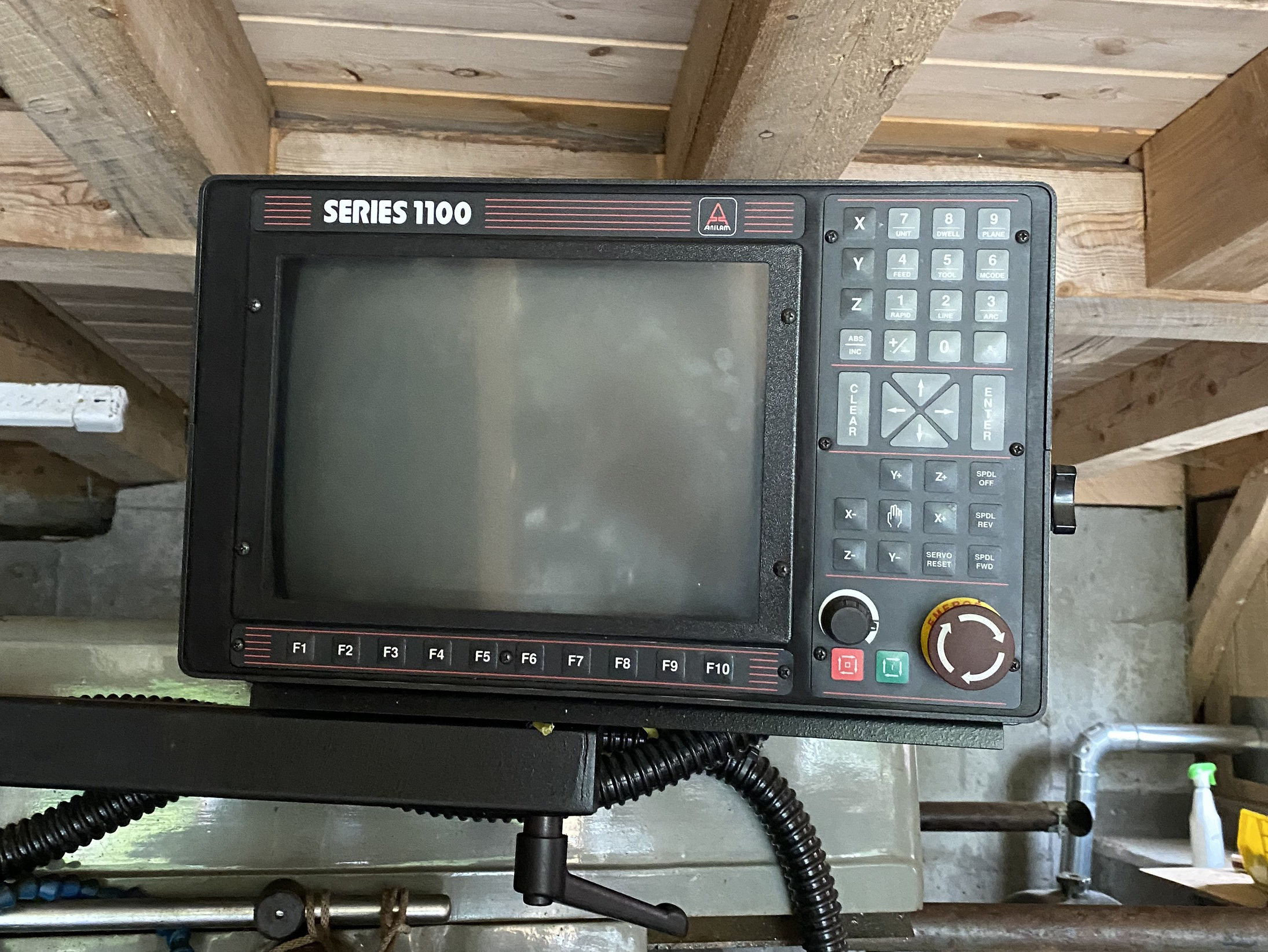
However, pre-2000s CNCs were very much like British automobiles. You celebrated your arrival, not your trip. It took many decades of iteration to create a truly intuitive user interface, one that decreases user error, programing time and ultimately improves yield. Enter the humble and chunky CRT control interface. It's everything you can imagine it to be, and oh so much more.
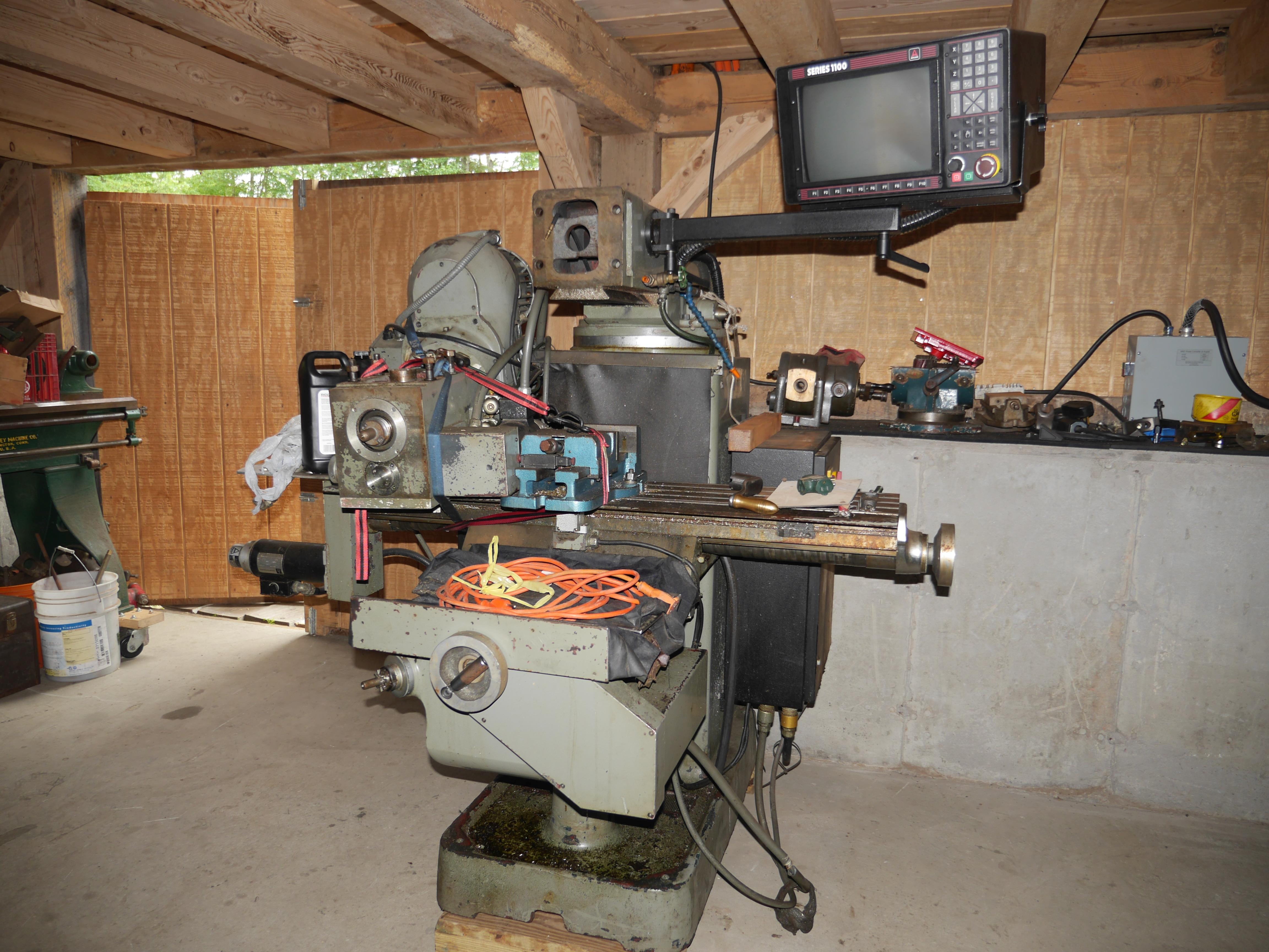
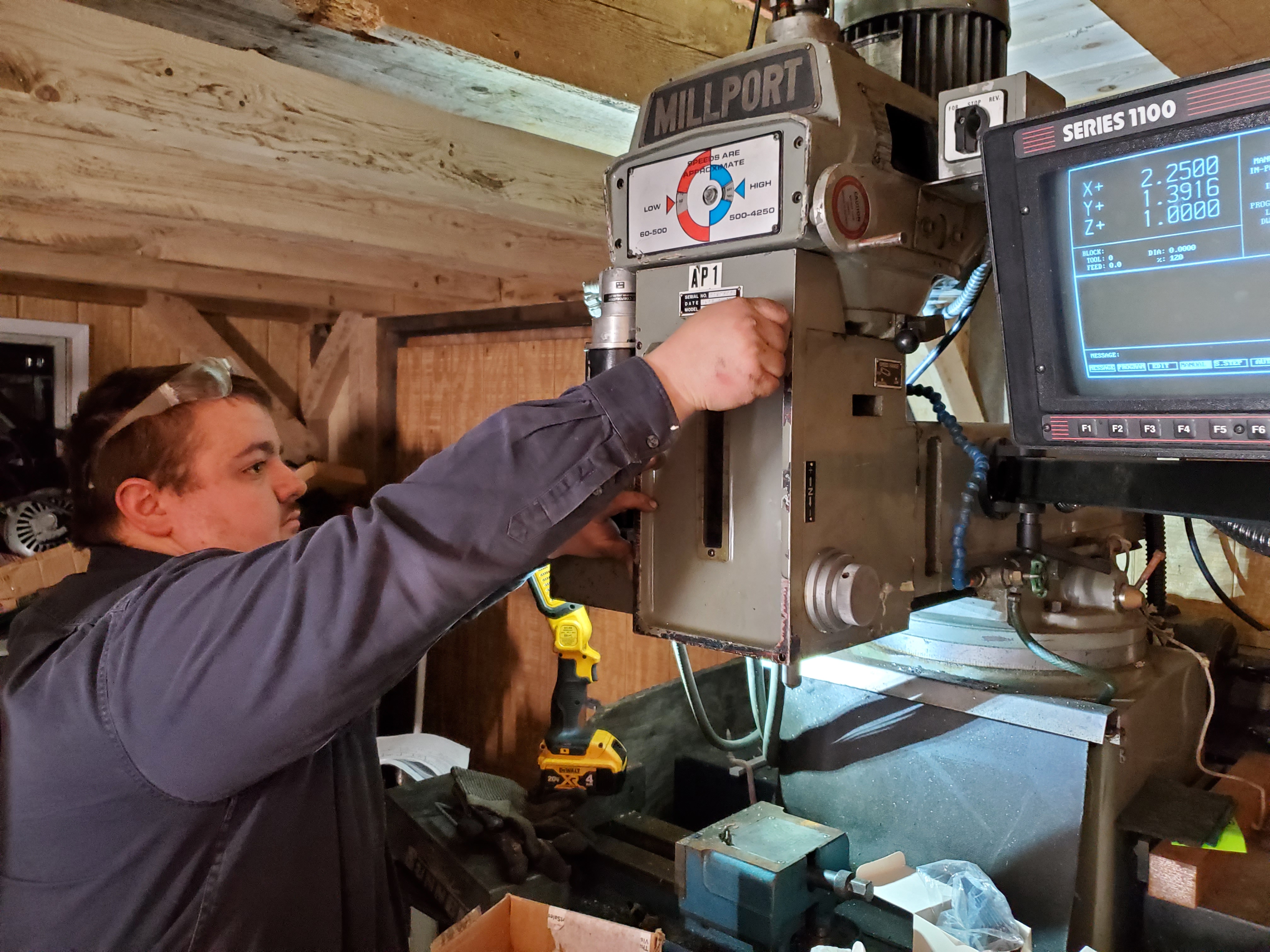
Milling Machine Overview
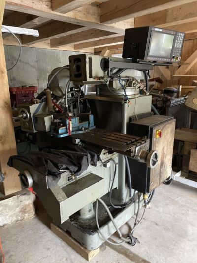
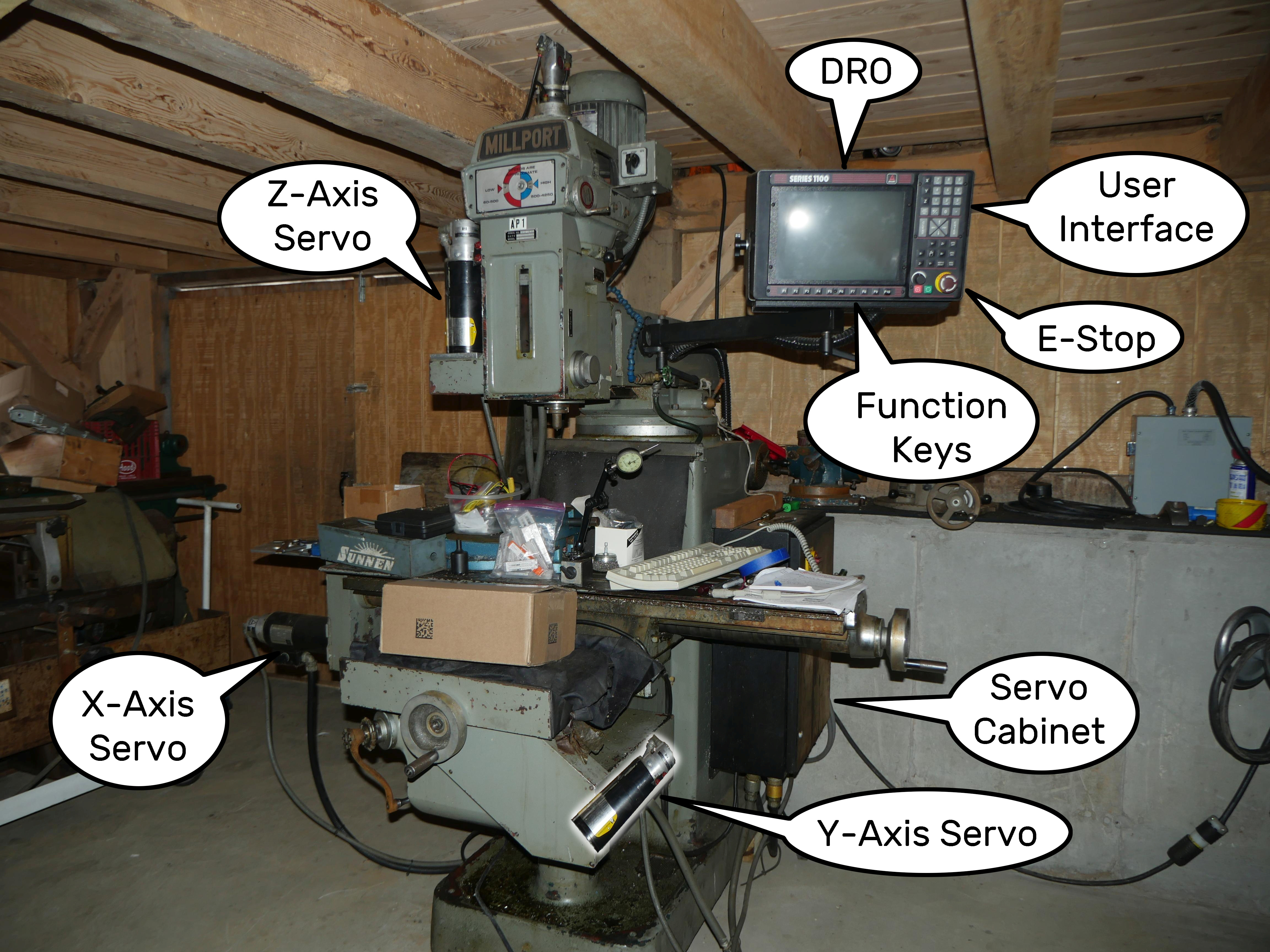
Not everyone has experience on a "Bridgeport" or a vertical mill, so an overview diagram is in order. On the left is a traditional vertical mill. On the right is this Millport vertical mill augmented with CNC bits. The Z-axis, Y-axis and X-axis each feature a modified casting to accept motorized input to the drive lead screw. Each axis has a Baldor servo motor and optical encoder tied to the control cabinets on either side of the machine. In this case, there is one cabinet for the control computer and one for power conversion / servo drive controls.
In the late 1930s, Bridgeport Machines Inc. introduced a revolutionary turret milling machine which was a more flexible take on the conventional rigid knee-and-column designed milling machine. Their unique design provided the "ability to machine a work-piece at virtually any angle and in any plane other than the bottom". The flexibility offered by this machine at the entry level price of $995 was a true game changer for machinery operations everywhere. Following WWII, Bridgeport quickly became the Kleenex of vertical mills because their machines were incredibly well built, reliable and gracefully iterated with subtle design improvements year on year. At one point, Bridgeport employed thousands of employees in Connecticut, but foreign labor rates would continually erode at Bridgeport's market position as the decades passed. Unfortunately, Bridgeport is now owned by private equity bros that think 1-2-3 blocks are a line of toddler toys produced by Little Tikes.
Millport is a Taiwanese machinery manufacturer that produced "clone machines" that look and perform very similarly to domestically produced machinery for a fraction of the cost. In the 1990s, Taiwan was not exactly known for tight tolerance production machinery, so Millport implemented an off-the-shelf servo motor control system from Anilam that featured Baldor motors as a way to gloss over QC issues or imperfectly ground ways. That was certainly one way to entice new customers.
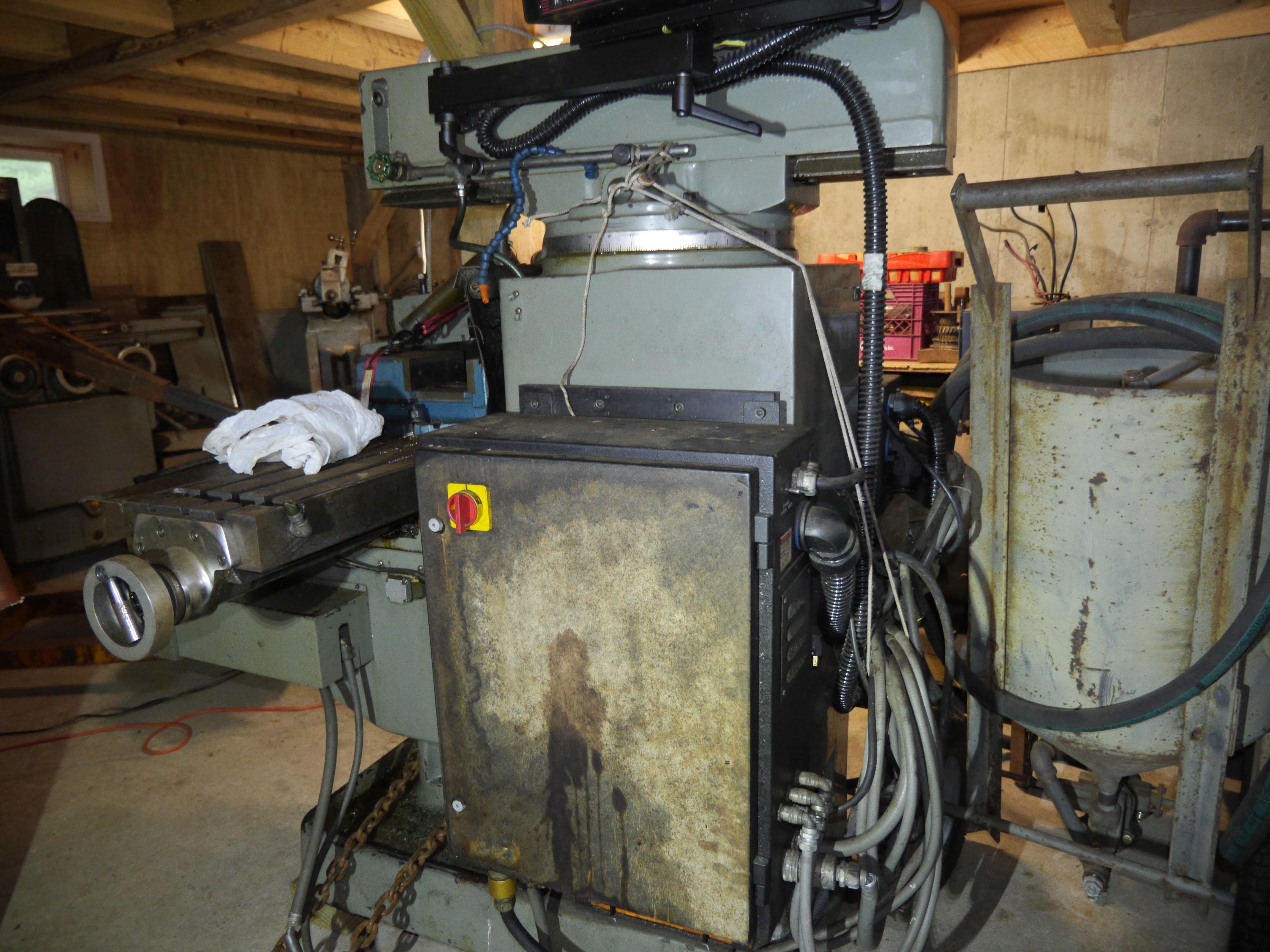
Sealed boxy control cabinets are a tell tale sign of production equipment. The idea is to isolate sensitive electronics from the operational environment, especially one chuck full of very conductive tiny metal fragments that can wreak havoc on exposed electronics. Boxes with rotary disconnect switches, such as the yellow/red switch shown on the servo cabinet, are common on production equipment to prevent the operator from accessing hazardous levels of energy while a machine is operating. These switches also feature punch-outs for physical locks which adhere to the OSHA Lockout/Tagout (LOTO) industrial guidelines.
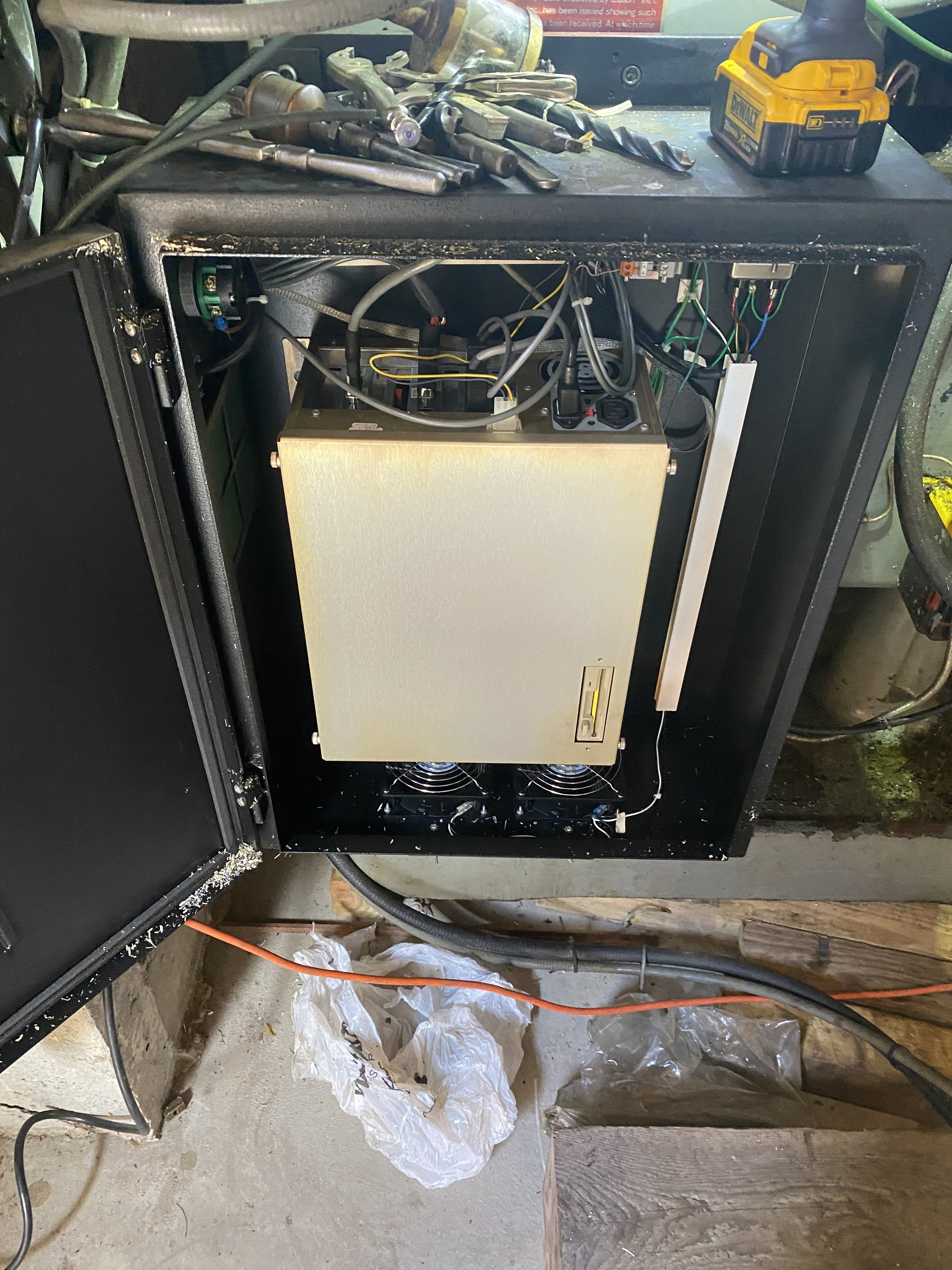
Computer Cabinet
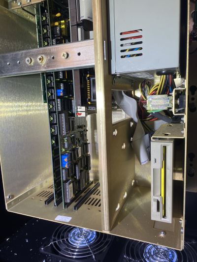
Initially, I left the servo control cabinet alone and focused on the computer control cabinet. I opened the cabinet door and thought the EMI gasket material was in poor shape. It was just metal chips. Wowzers. Several rear electrical grommets were loose and wobbly, leaving gaps for debris to enter, but at least the computer was isolated by an additional inner enclosure.
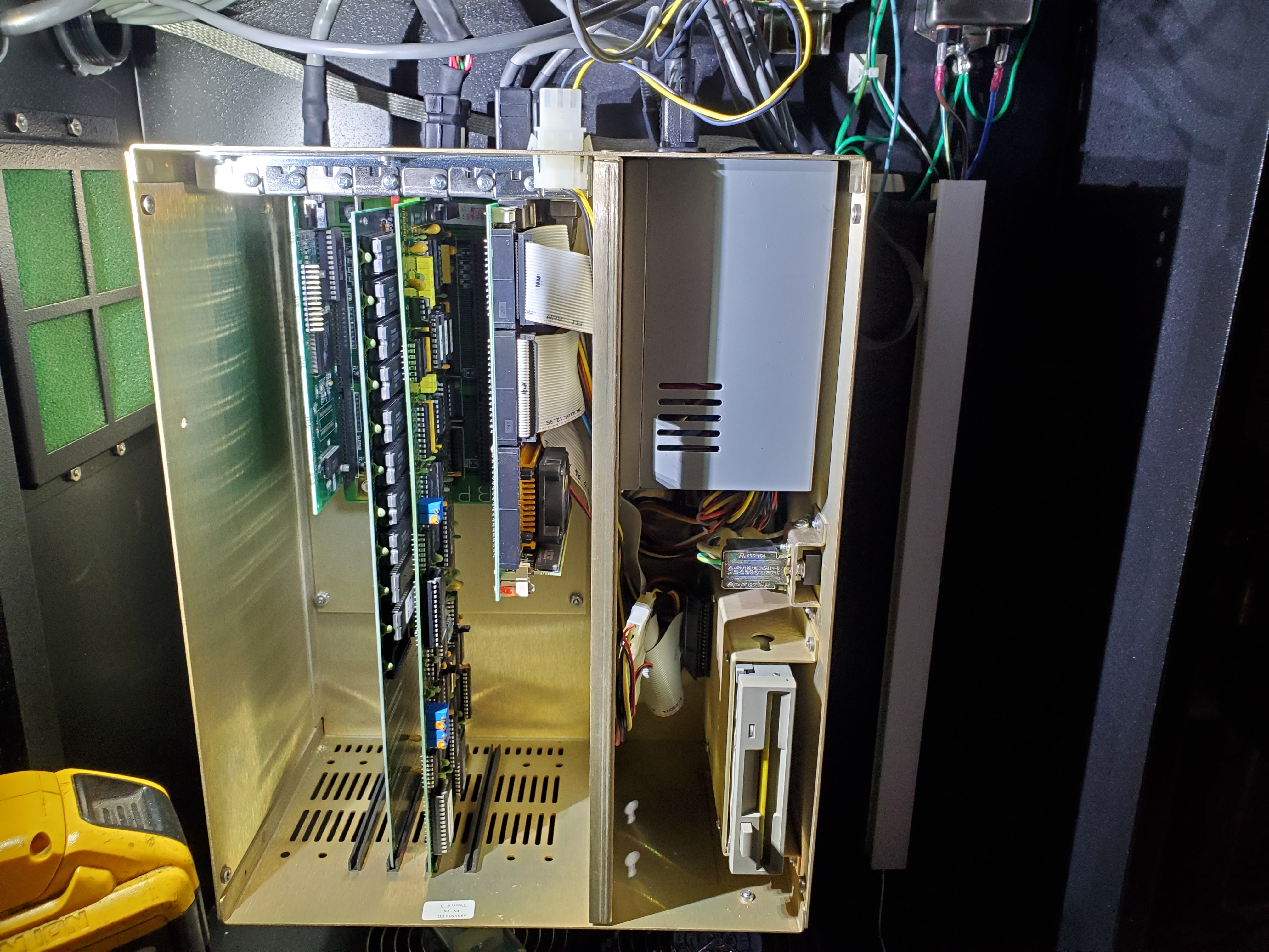
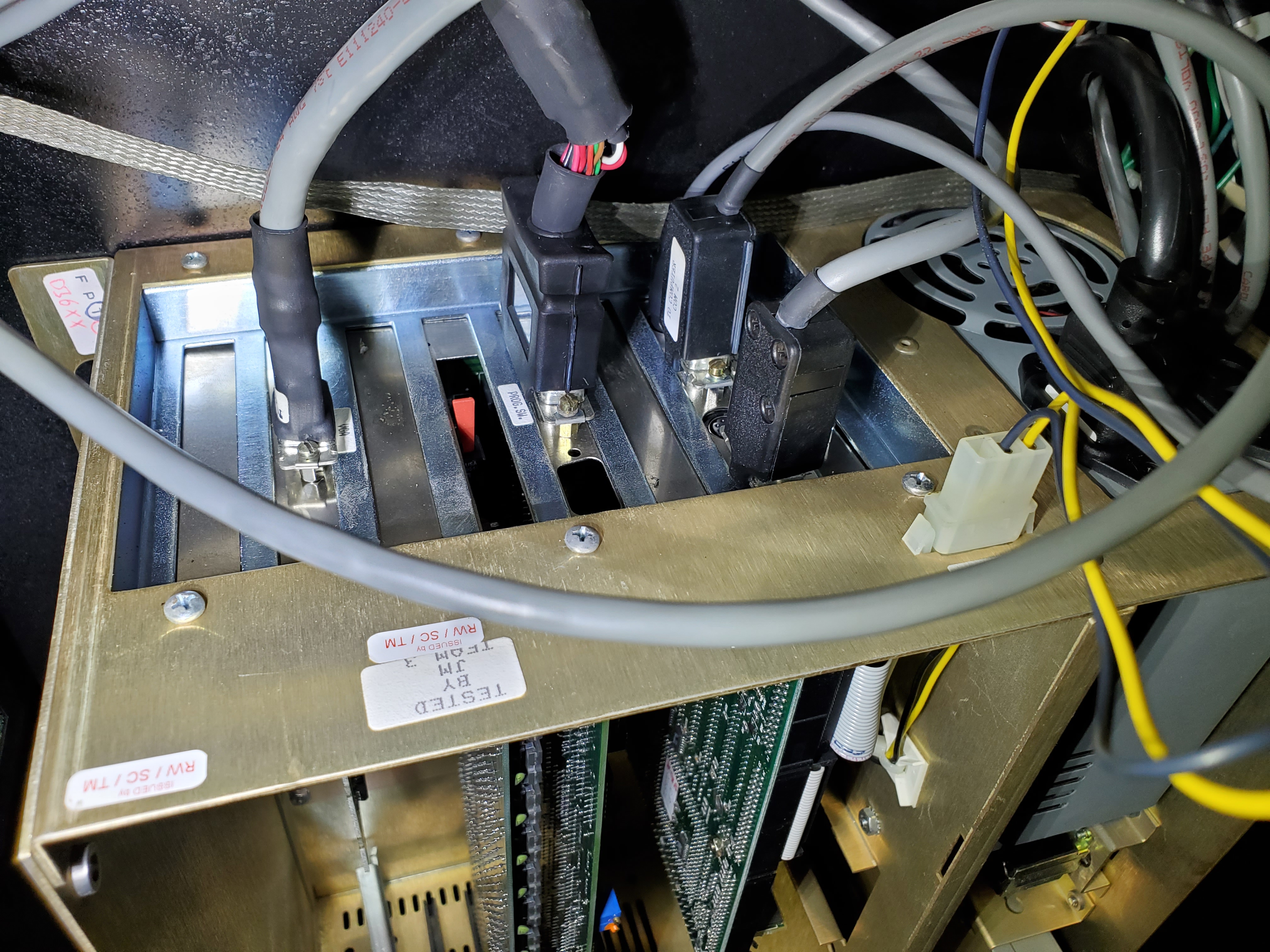
The computer was an AT-styled machine with an ISA backplane, an extended length ISA servo controller card, a video card, some kind of ISA memory card and a compute card. That compute card featured an Intel 486, one ram card, one floppy port and two IDE ports. A Palm Treo easily outshines this build in raw compute performance. Noticing an unpopulated IDE connector and space besides the floppy, I grew concerned the machine we spent all day moving had no operating system, control software or prayer of working.
Once we wired up a 230v drop, we decided to turn on the machine as is, even though I saw sweating just looking at the condition of the control cabinets. Somehow the CNC booted and the PC made a bunch of beeping sounds. As expected, the bios threw a fit because it still was expecting the Backstreet Boys to be topping the US Billboard Hot 100 charts.
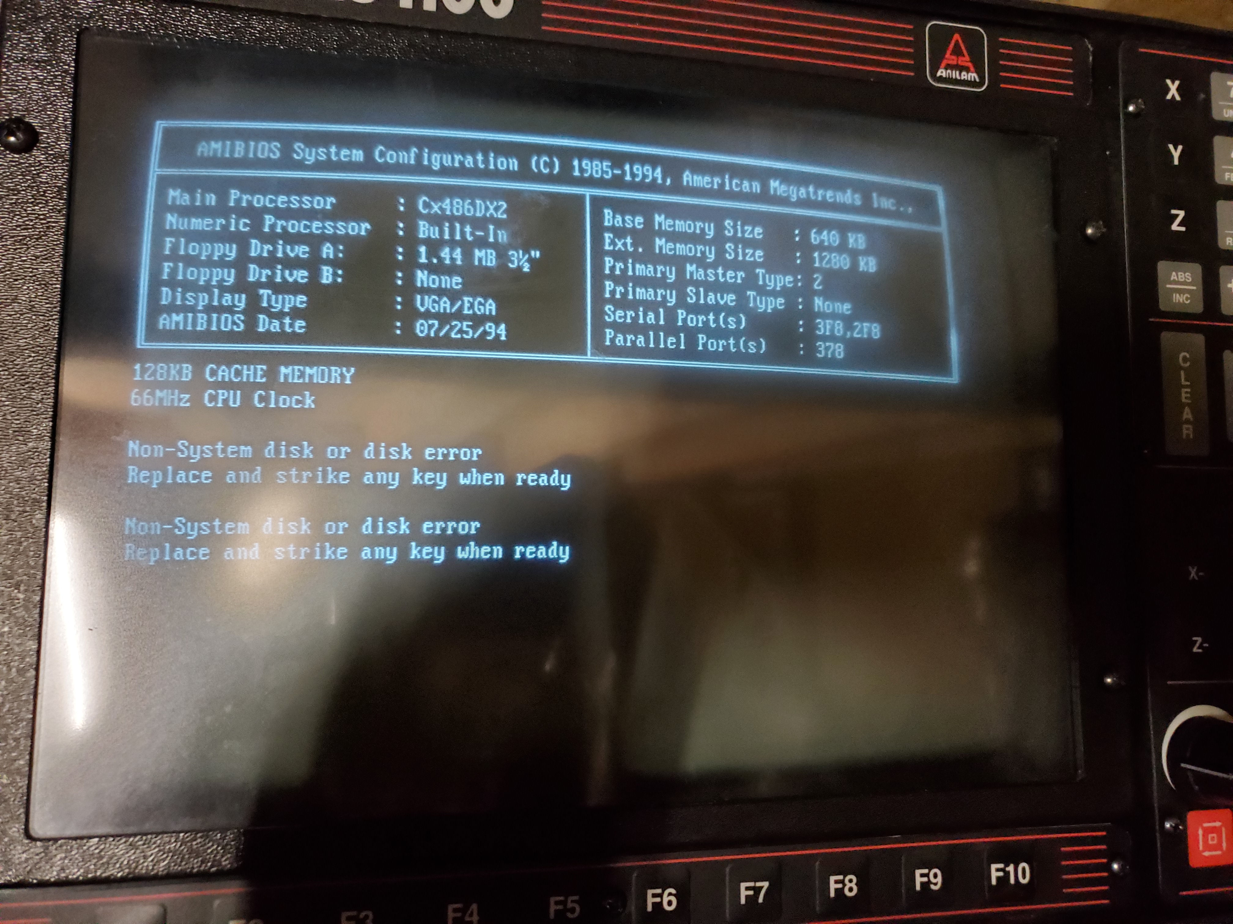
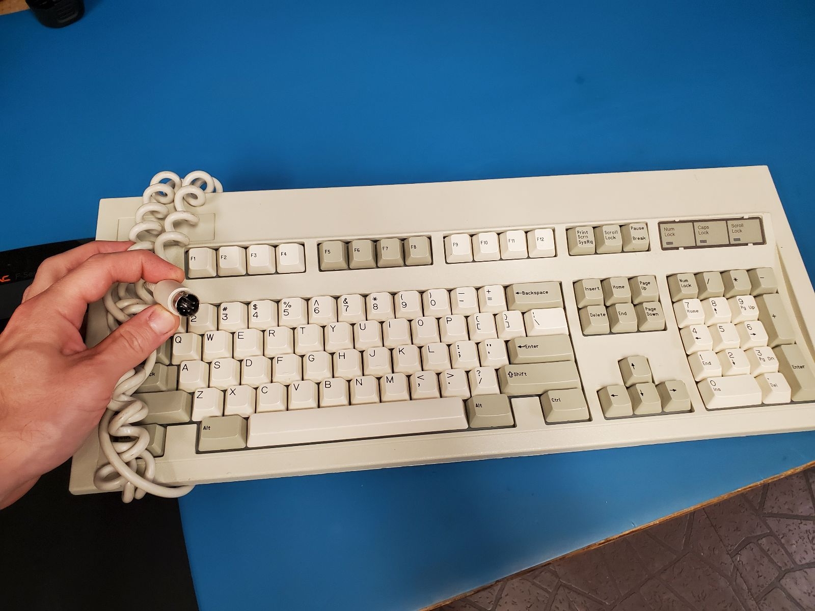
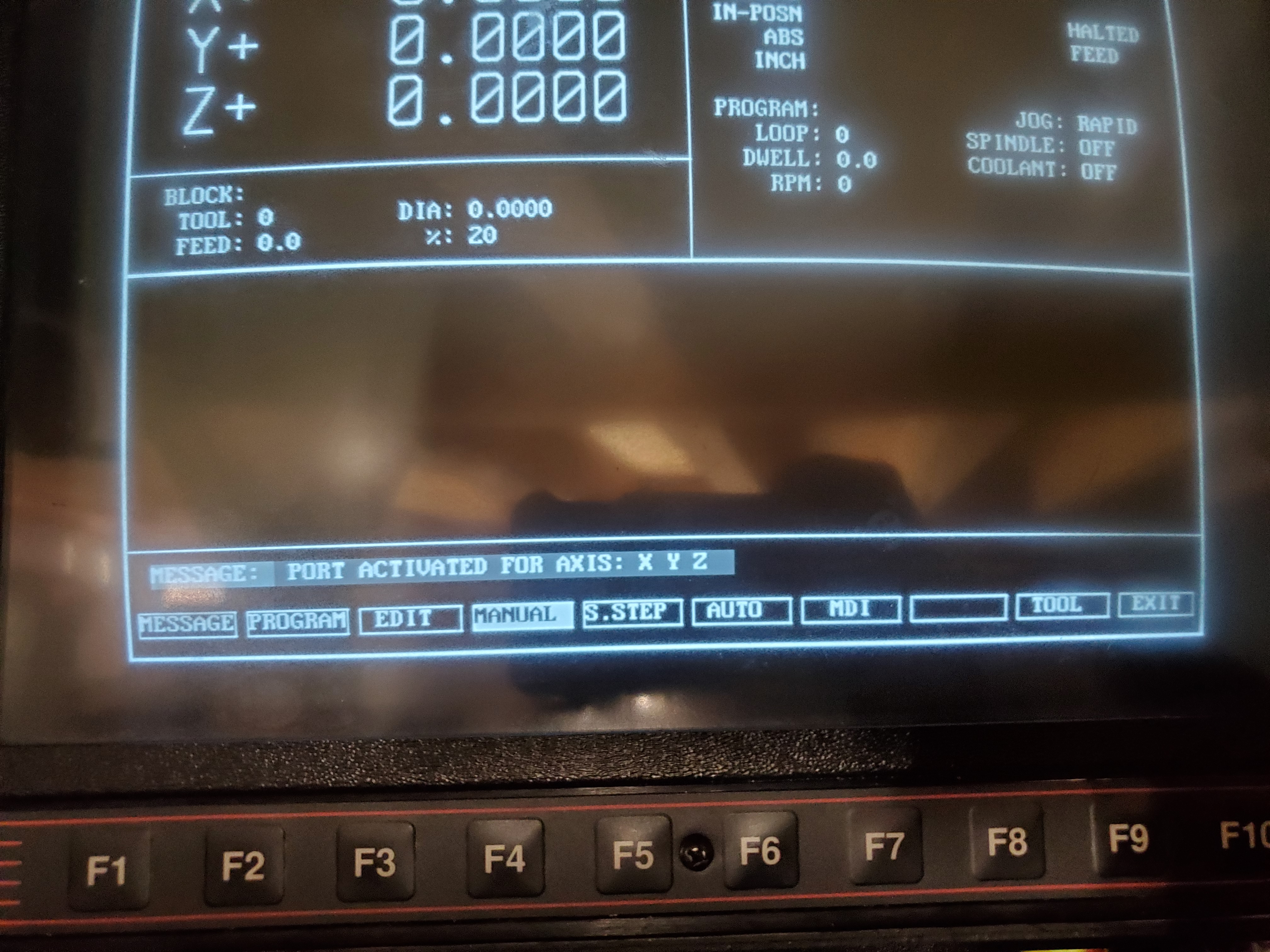
To suppress the bios warning messages, you need an external XT/AT keyboard plugged in since the F# keys on the DRO display did not function at bios boot. The F# keypad on the DRO display must clearly share the XT/AT keyboard input and the XT keyboard just enumerates first before the F# keypad. This means when you finally bypass bios with the external keyboard attached, the F# keys on the DRO don't work while using the CNC software. There is no hotplug in DOS, so you completely lose DRO F# keypad menu functionality whenever you bypass bios.
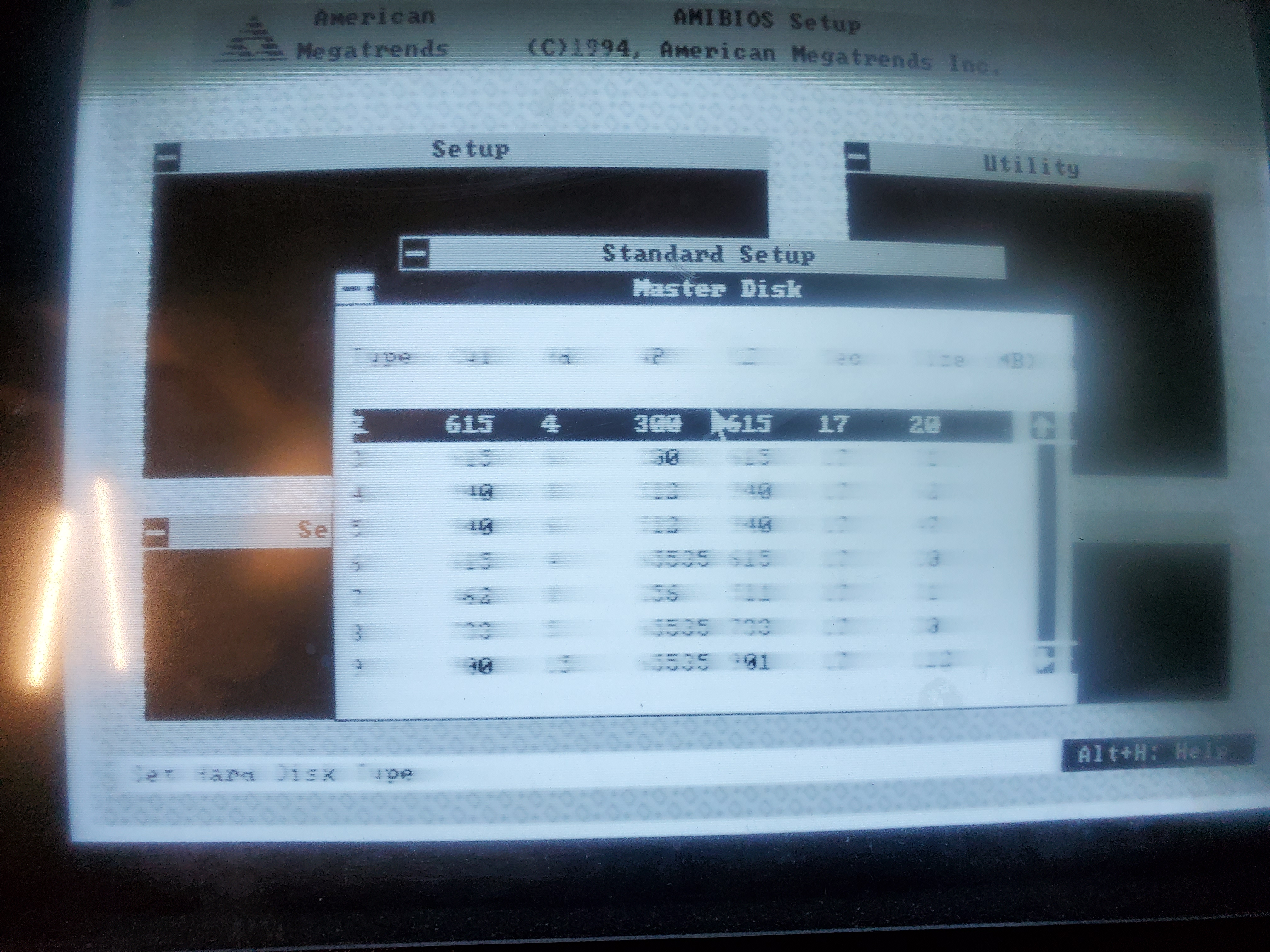
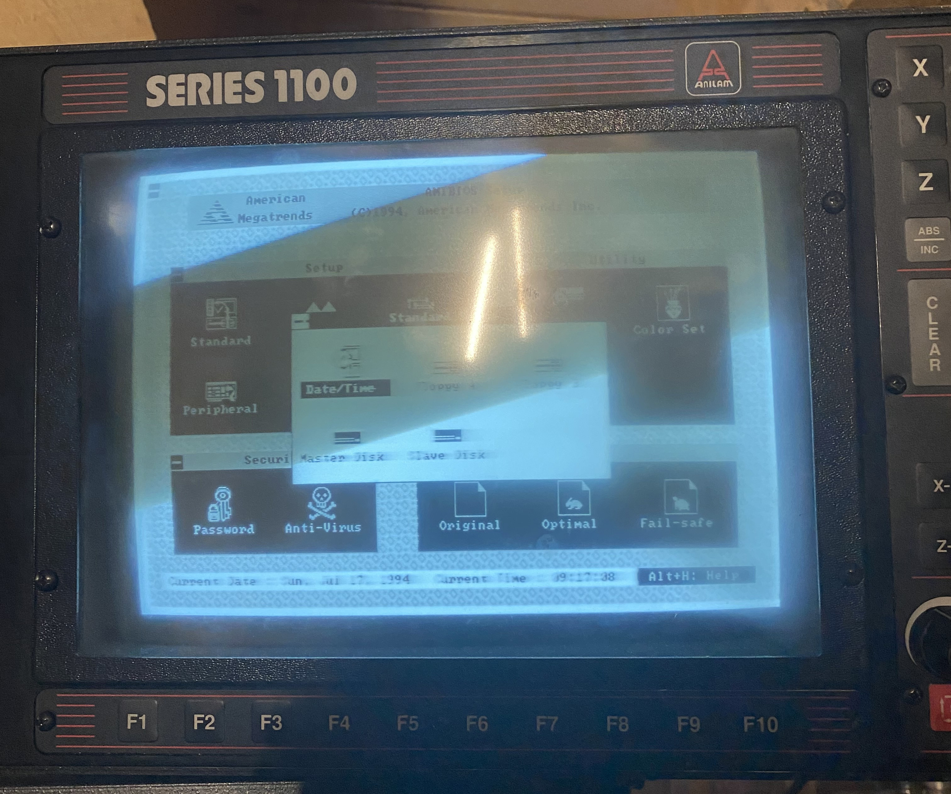
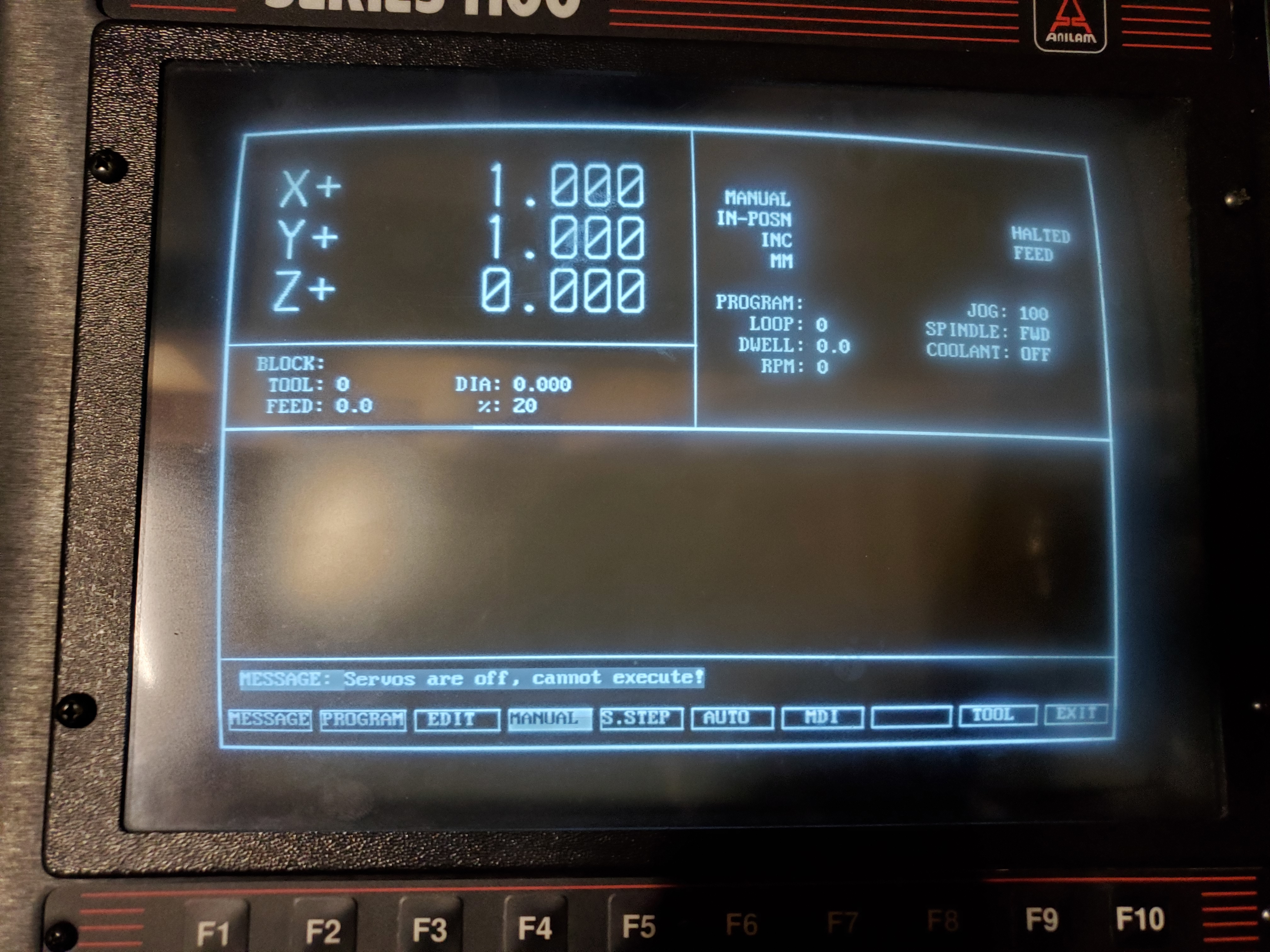
The bios screenshot is blurry not because I used a cellphone cam but because the CRT display is on its last legs. It struggles to display large groups of text. The CRT is easily older than me, and I can imagine all of the capacitors on the CRT control board are toast or the focus on the flyback needs adjustment. A ~10in VGA LCD is a more viable alternative all around. For one, I had to get into bios and tell the silly machine to stop booting from floppy first. After some archaic bios Konami code combos, I was able to bypass the warning messages and force the machine to boot.
F1 to bios
Tab over to end dialog box
Load fall safe defaults. Esc. Save.
It reboots, goes to bios. Hit esc. Don't save changes.
It boots, hit f1.
It starts loading 1100 software
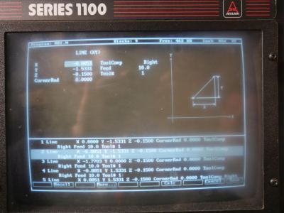
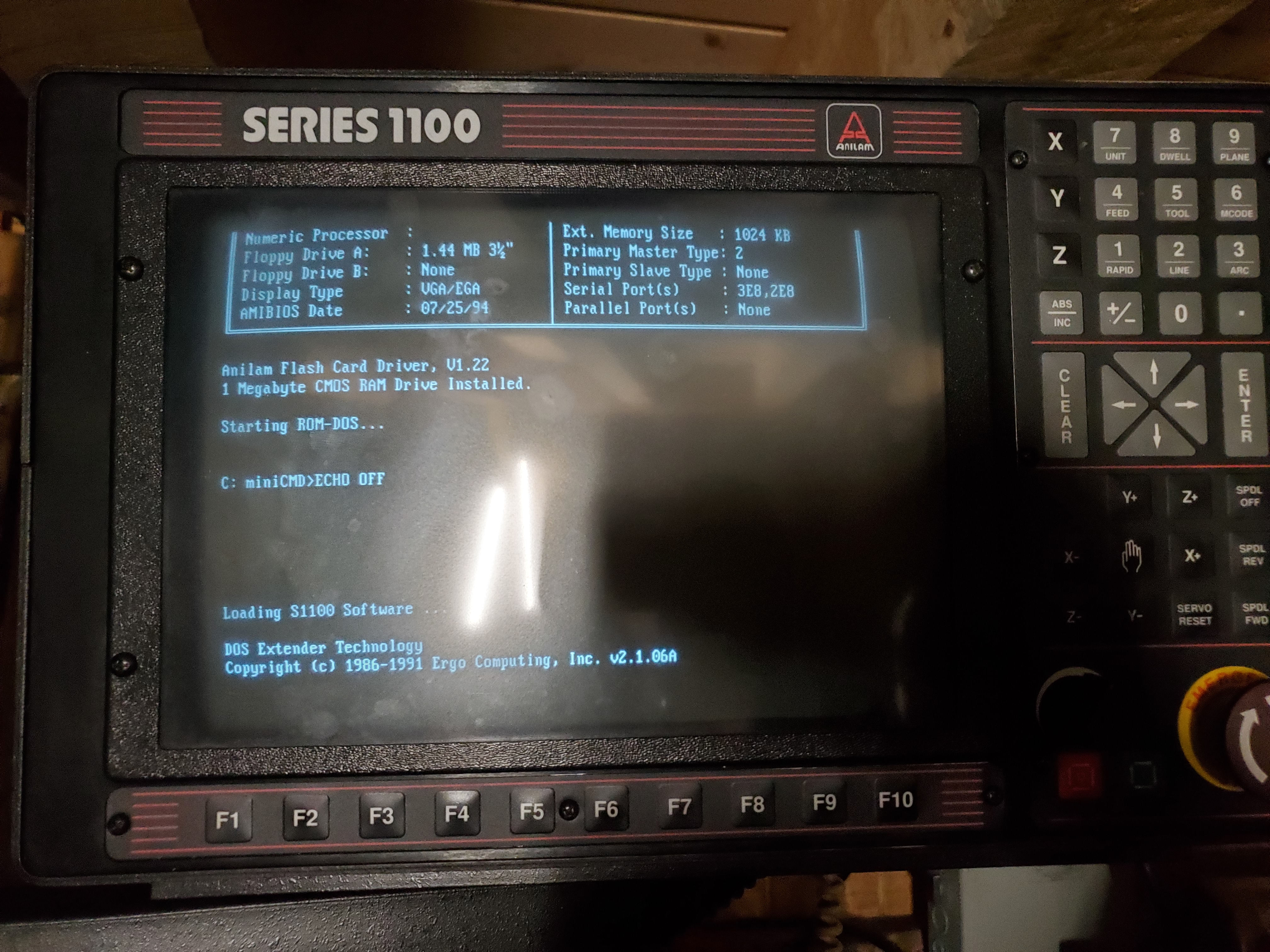
I was surprised how fast the CNC booted once the bios fiddling was done. Under a minute for a 1990s cnc isn't that bad, and if it had a mechanical hard drive it would have been closer to 10 minutes. It still amazes me that a 1 Megabyte Flash card was adequate for running CNC controls on top of DOS. What happened Microsoft? The Anilam S1100 software loaded and initially the F# buttons did not work, which made menu navigation a hassle.

Surgery
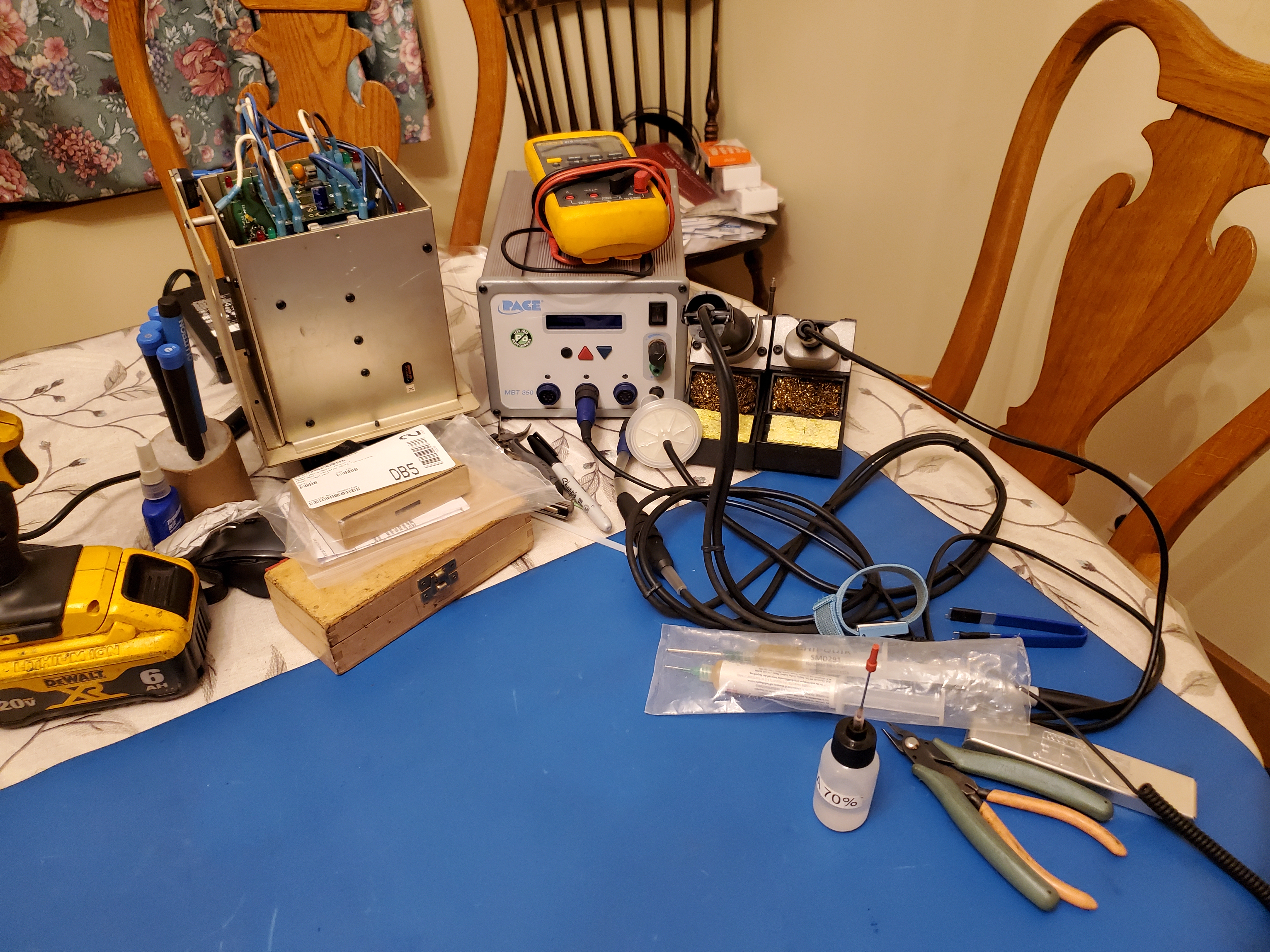
Spending a minute every boot up fiddling with bios to bypass warnings and having non functioning keys is not tolerable for a production environment. The compute card had a scheduled appointment with the resident EE at 9pm, and boy was he on staff with the right tools at hand. I brought up my portable ESD mat and some my my Pace equipment and the star of the show, the solderXtractor. Manual solder suckers are very fiddly. This trigger actuated solder sucker makes the process substantially easier and faster.
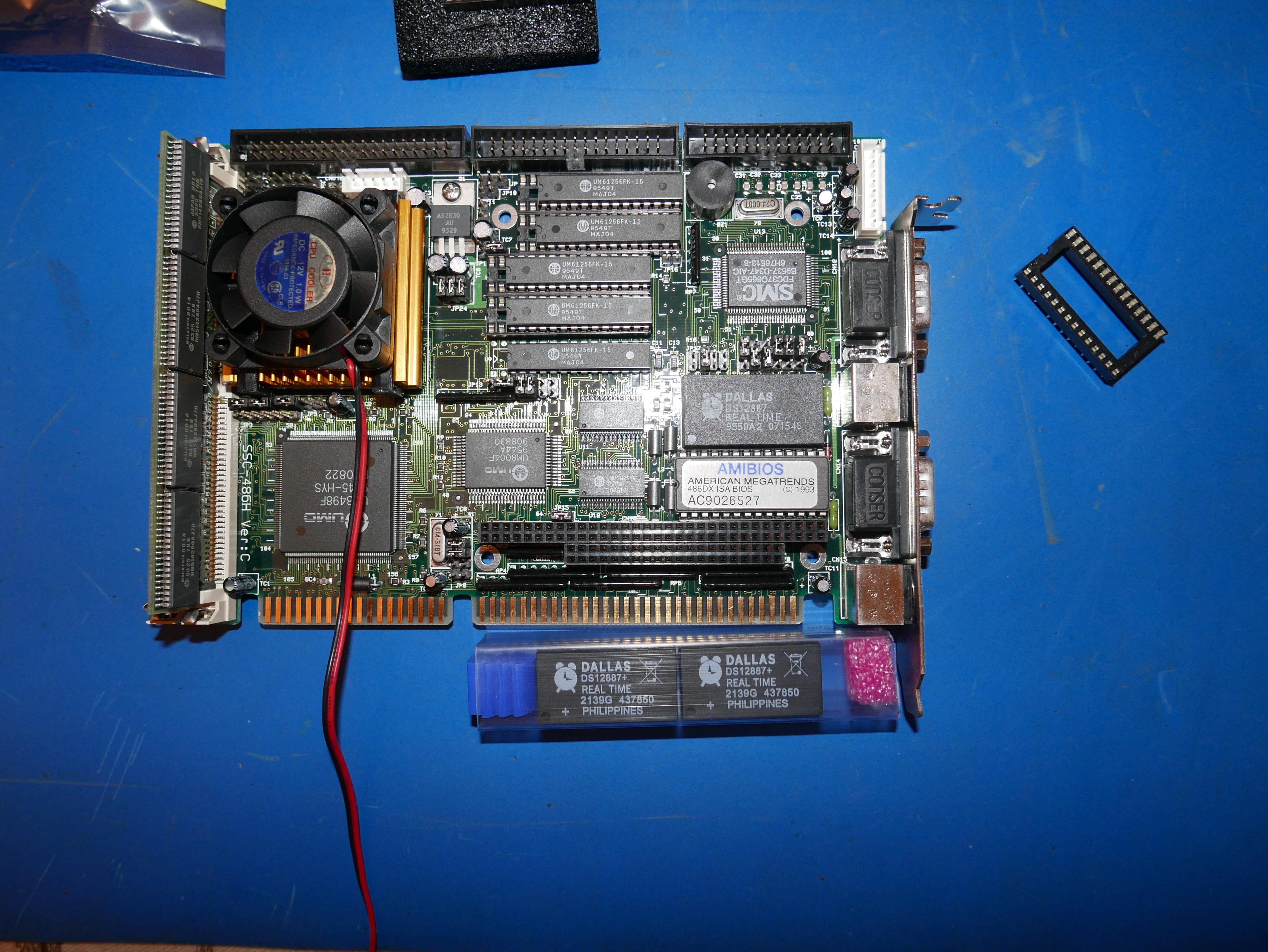
As expected, the dead Dallas RTC/NVRAM module that keeps the date & time was soldered directly to the board. As a matter of course, I added a DIP socket, but I can't imagine this machine is going to be in service for another 10 years with this archaic hardware. Luckily, you can still acquire these DS12887+ clock chips from Maxim Semi (now Analog Devices). Props to Analog for keeping the iconic Dallas clock logo.
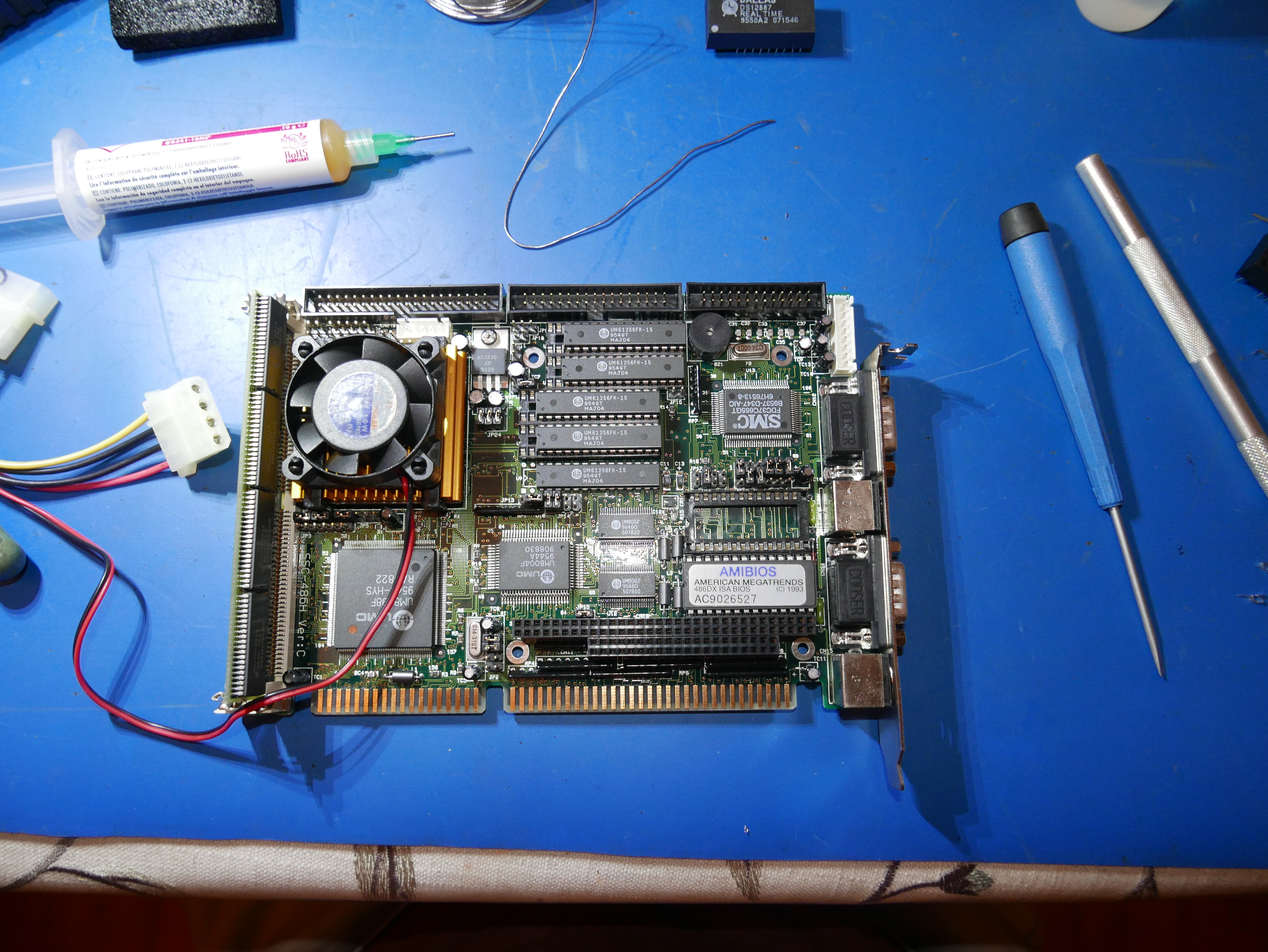
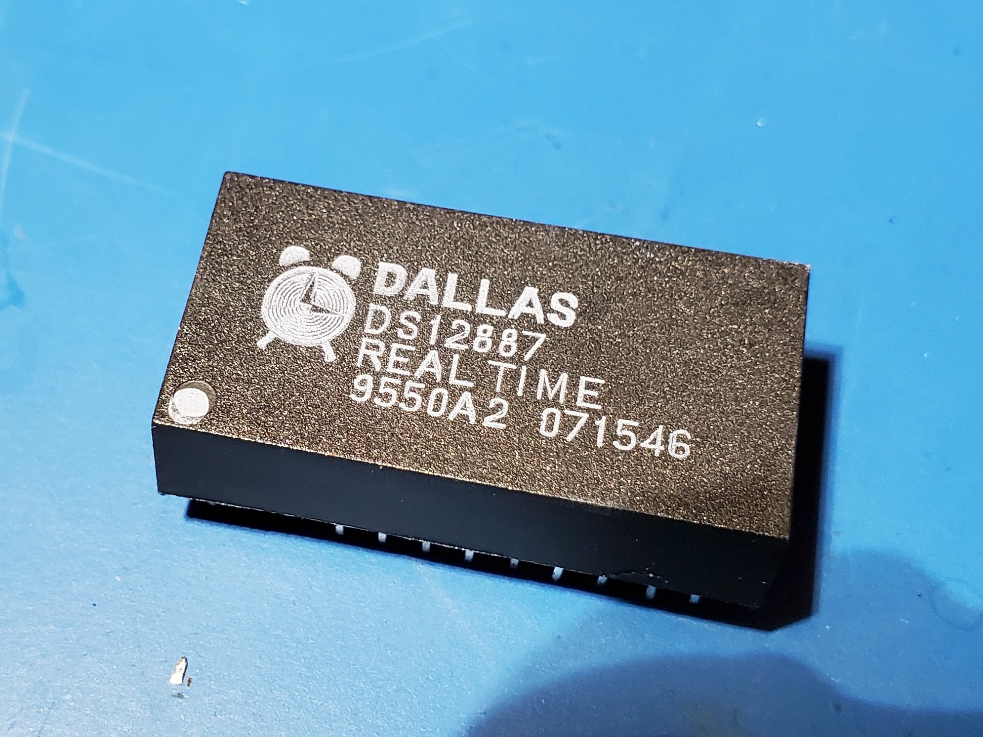
Replacing clock chips can be a bit sus as you don't know if the on package ROM contains any valuable data, such as calibration or positional data. Since this was a generic compute board card, it is extremely unlikely it was used for such valuable data, and was just used for bios date / time. If the clock chip was on an Anilam controller card, I would have taken more drastic measures, such as digging into the epoxy package, severing the old primary lithium cell leads and adding a battery holder on top. Now just to change the date & time in bios.
Back In Action
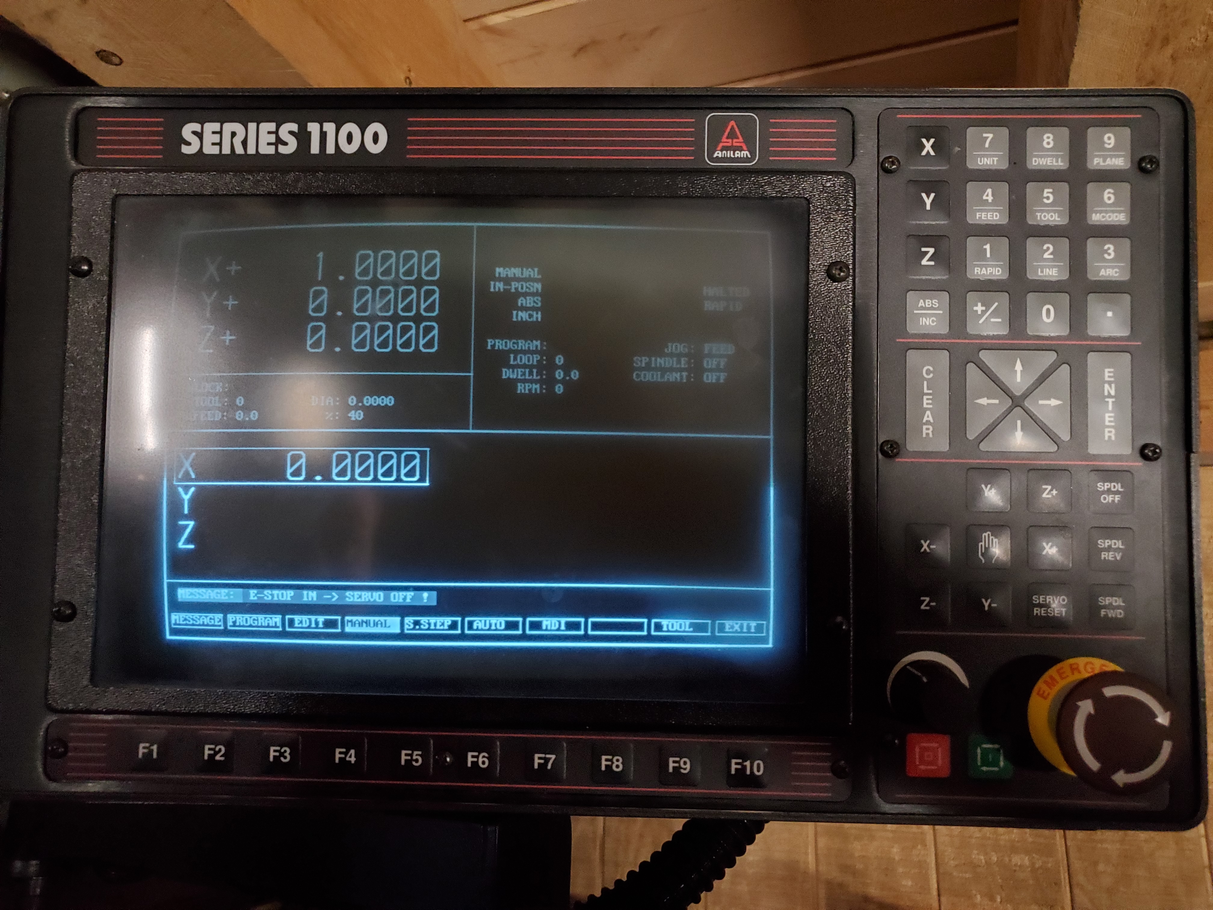
Now that bios settings can be saved, the clunky external keyboard went on hiatus and the Anilam 1100 series software menus became accessible. Neat. The servo motion control boards were picked up by the Anilam controller and things were looking good.
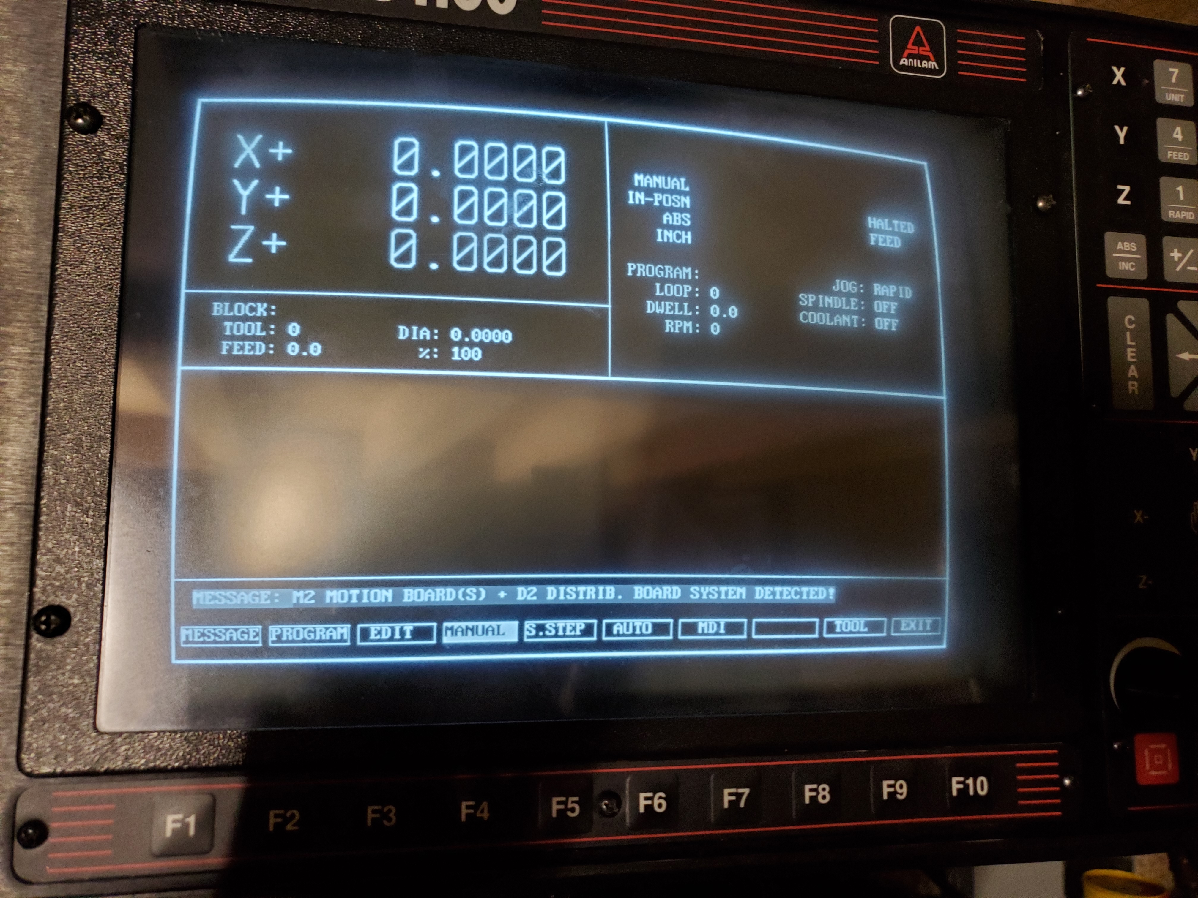
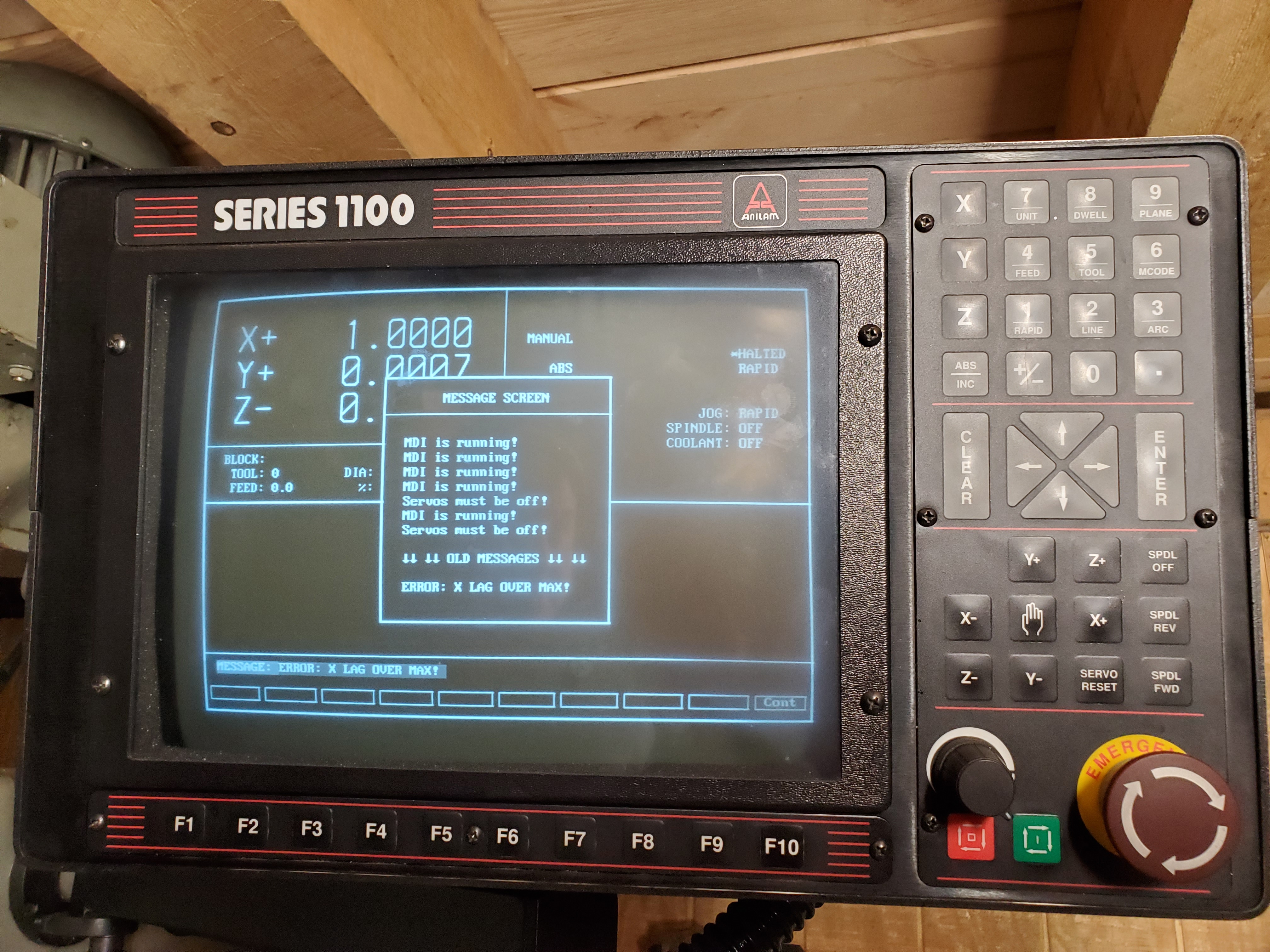
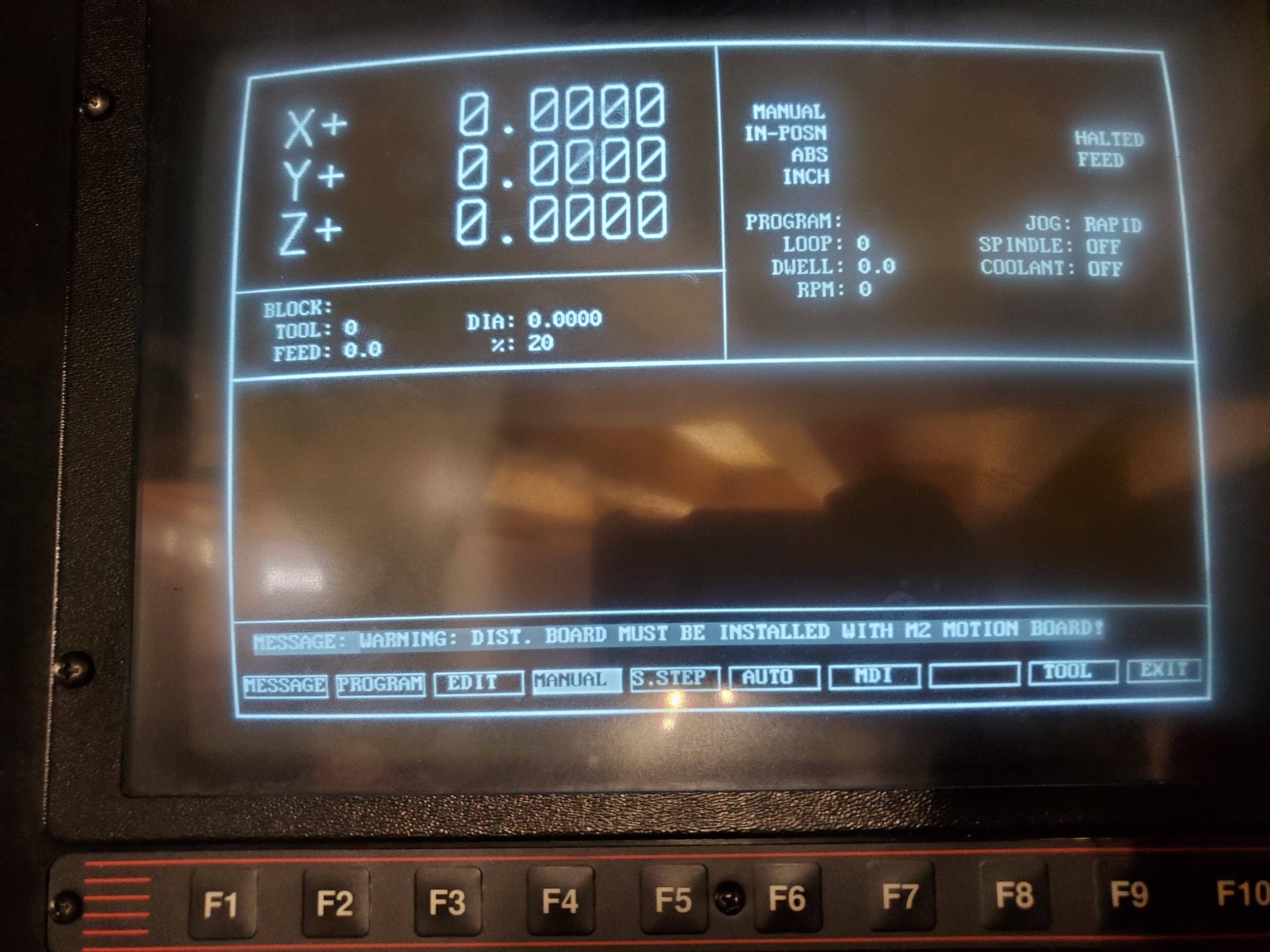
Then the errors started rolling in. Servo Off error. E-stop error. X-lag over max. Distribution board error. So many buttons, so many errors, what did they all do? I started digging through sub menus and felt like Dee-Dee. Luckily, one brave sole posted up the Anilam 1100 series troubleshooting guide. The references finally made sense! I also hunted down an Anilam 1100 programming guide too, which felt like hitting the jackpot.

The random X-Lag and dist board errors were most troubling. These two errors occasionally showed up for unknown reasons so I spent more time digging through the troubleshooting guide to find solutions.
The E-stop error seemed off because the system did not respond to the E-stop regardless of what state it was in. The Servo-off error was anticipated as it was likely related to the faulty E-stop switch, or so I thought. Tremendous thanks to this lone Anilam interface soldier on the net. I would have never guessed that in order to enable the servos you had to twist the e-stop in a right-left-right configuration before pressing in the E-stop. Shown at 1:07 in the below video. What a boondoggle.
Servo Cabinet
After thoroughly troubleshooting the computing portion of the CNC and hitting what seemed to be a break point, the bare metal side started calling my name. Time for some Rust bois. It looks like the previous owner had some serious difficulty with this machine as the servo cabinet was absolutely plastered with metal chips. Each cabinet had provisions for cooling fans and scotch-brite-like mesh filters so it's not an obvious design flaw. Clearly, the machine was running for a while with the cabinet doors open.
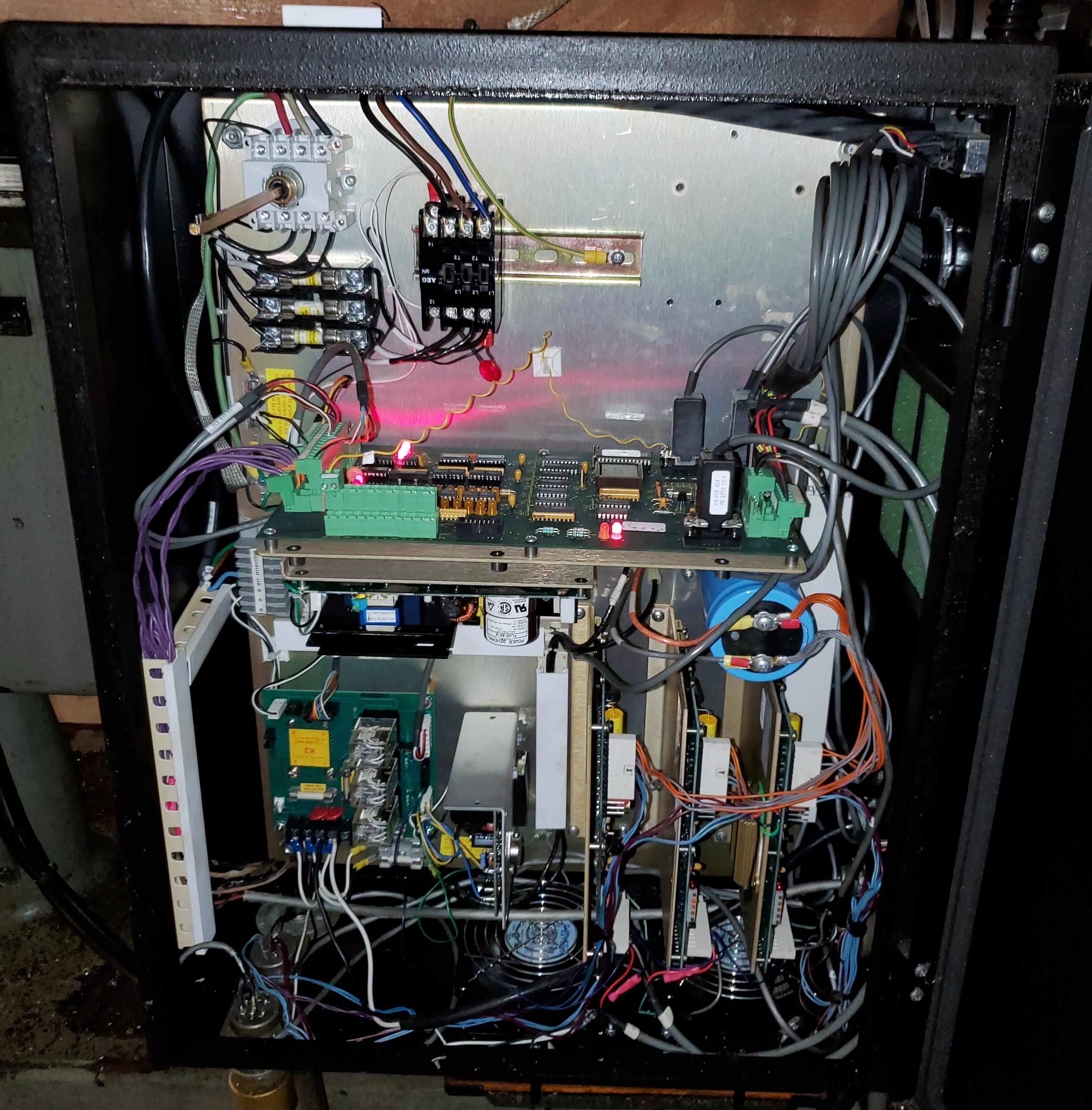
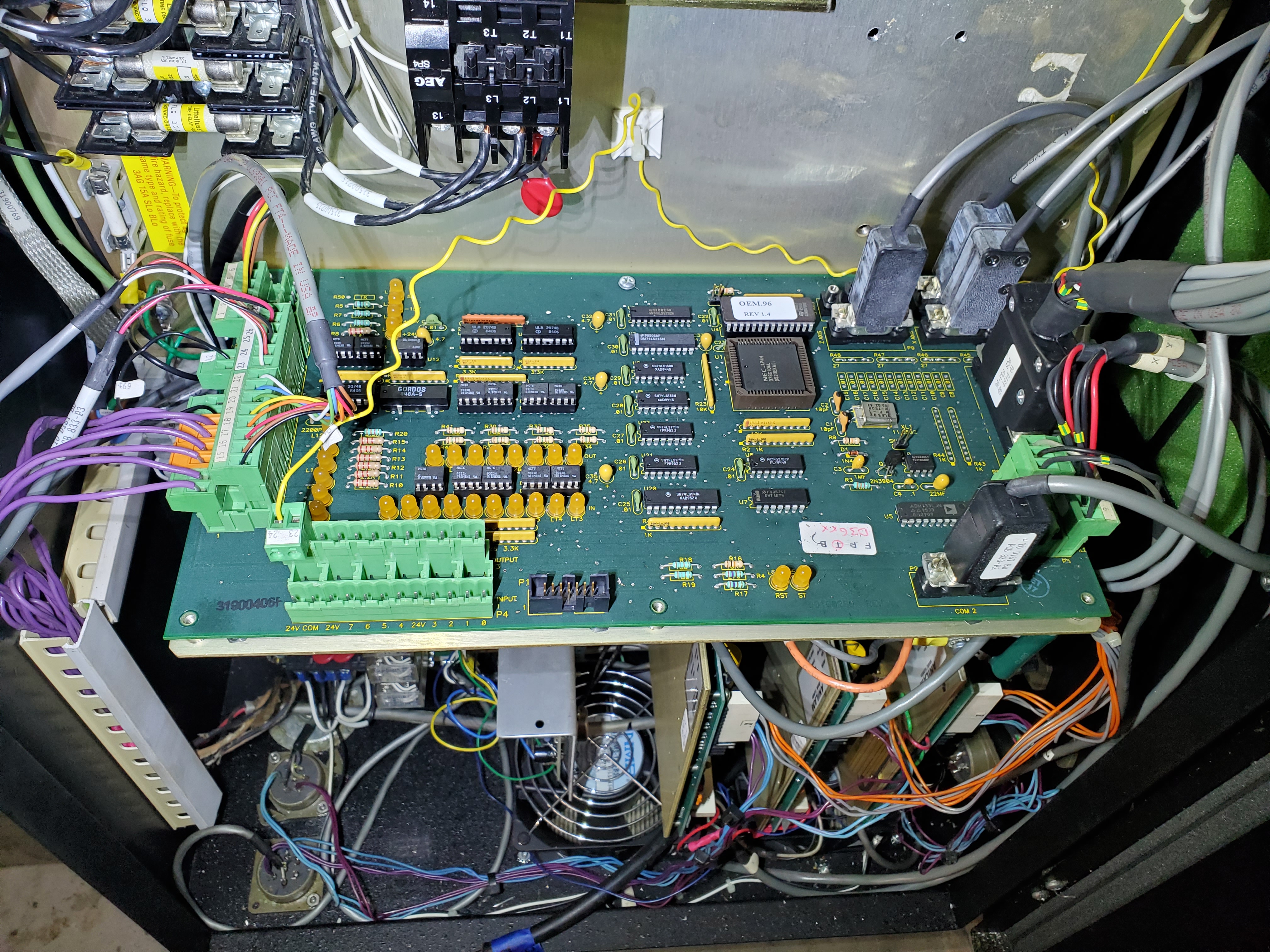
Servo Cabinet Insides
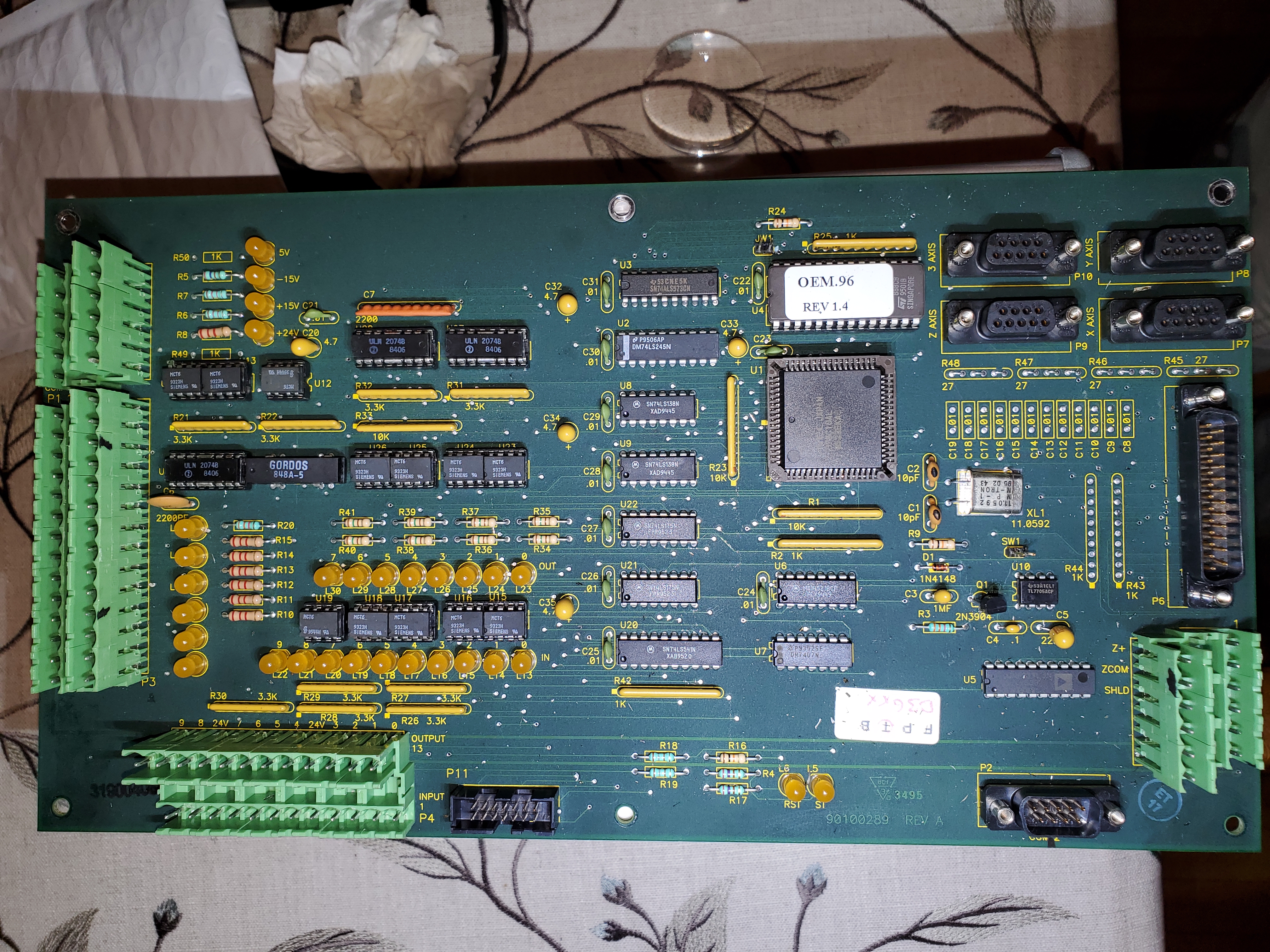
In terms of topology, you can clearly see power conversion components, three separate yet identical servo controller cards and one main PCB, the S1100 Distribution board. More on that PCB later. The power related components are properly chunky with industrial equipment, as noted by the large filter cap, socket-able relays, Bridge Rectifier and fuse holders placed throughout the cabinet.
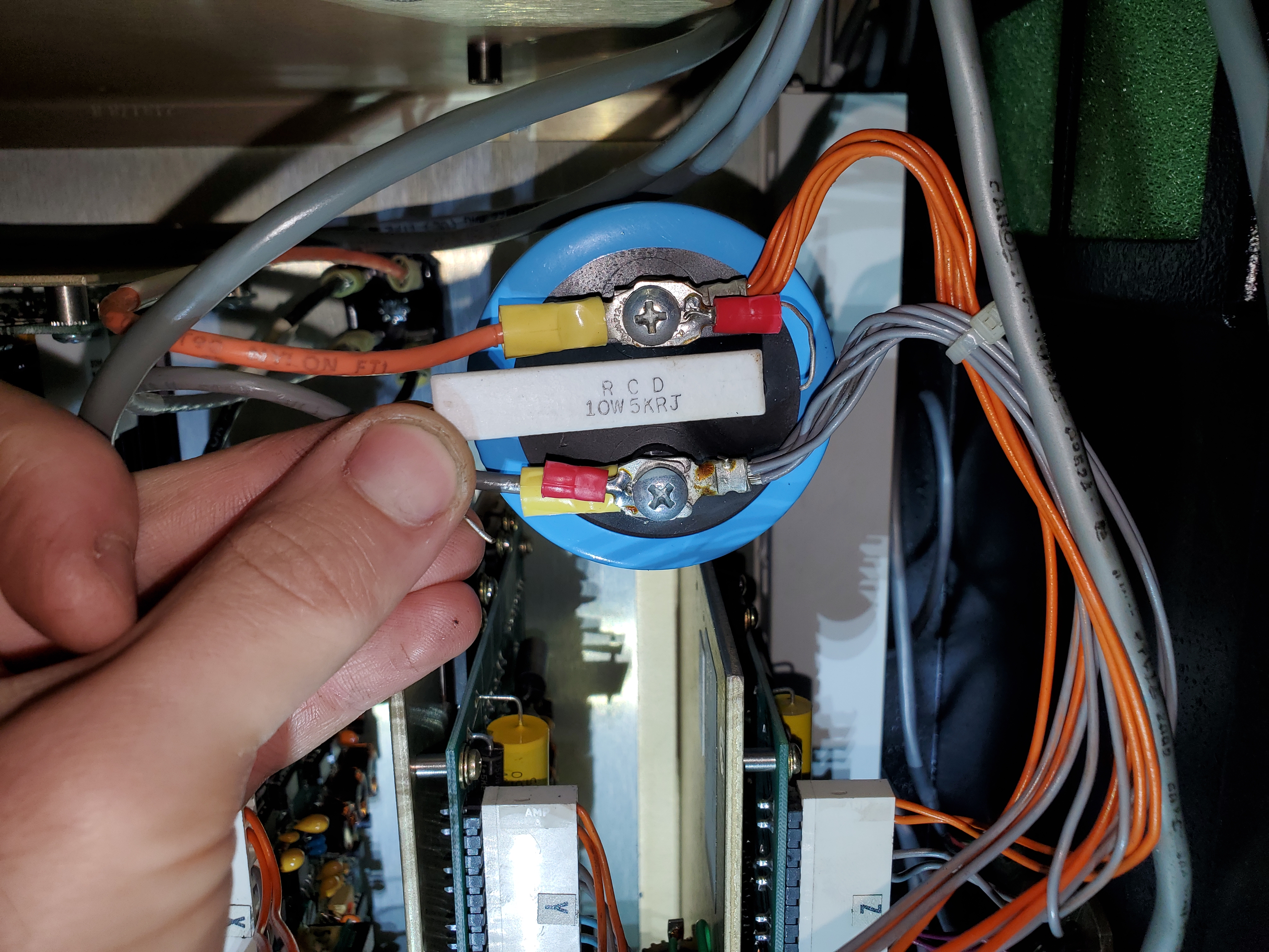
The line filter cap caught my attention first. Exposed leads from a broken bleed resistor is not a good look. Being the resident collector of weird and eclectic electronics, I just happened to have some spare 5k 10w resistors on hand. Warning: make sure you properly de-energize line capacitors before working on any electronics. The bleed resistor is supposed to bleed this cap in a few minutes if it was present. The shear volume of electrons in that cap will 100% kill you. Take precaution.
Uh, That Ain't Good
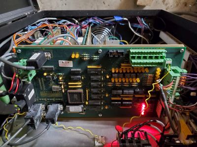
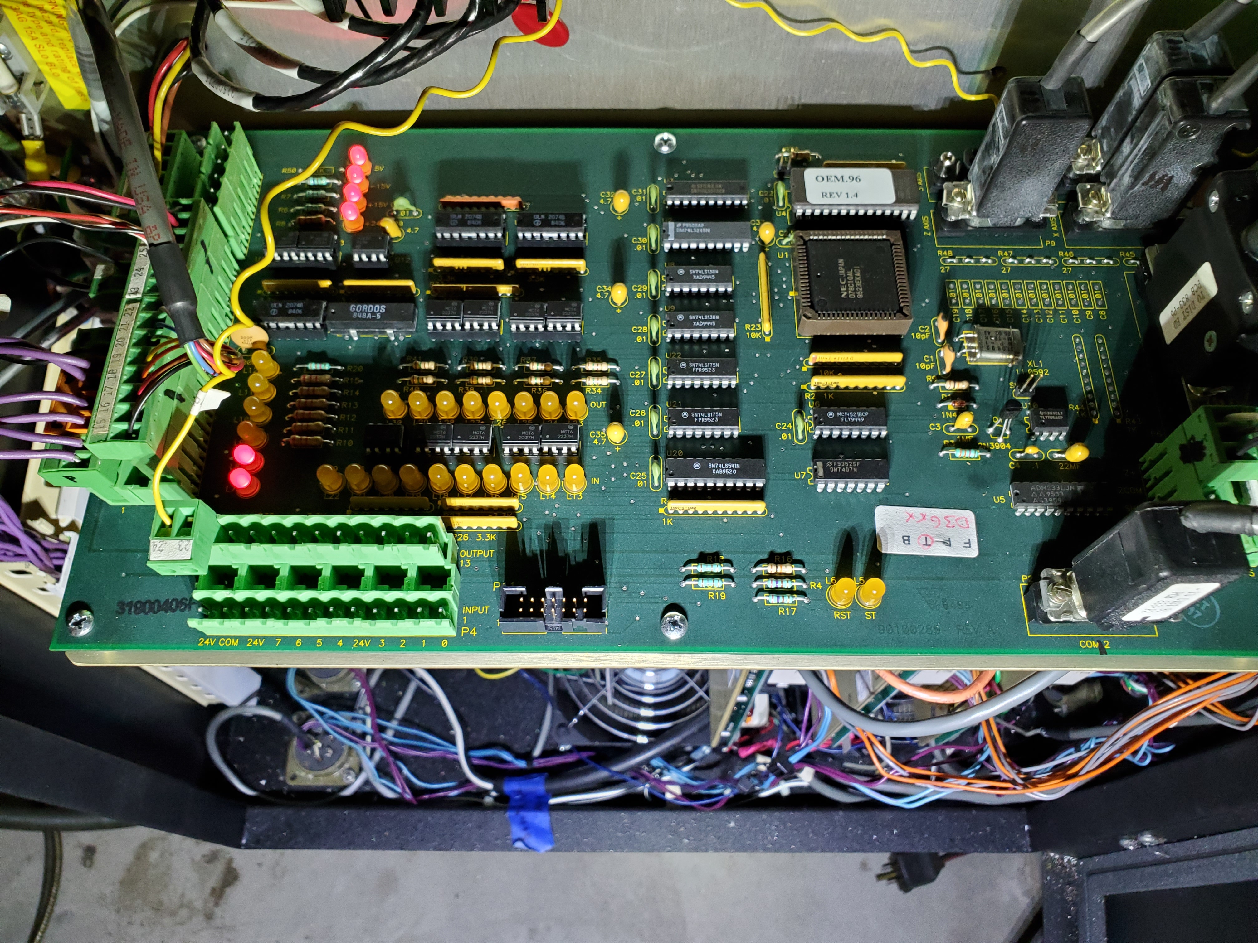
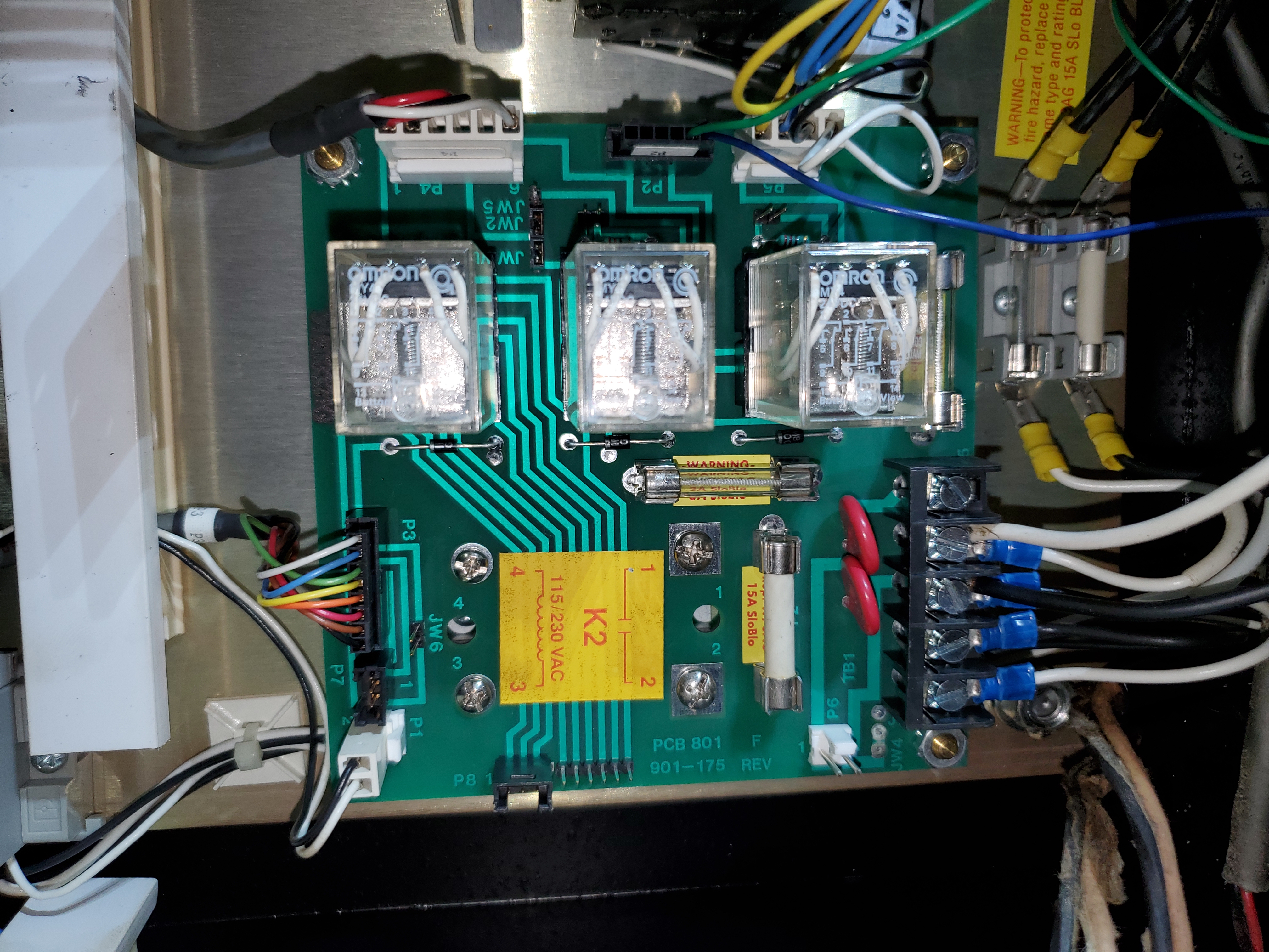
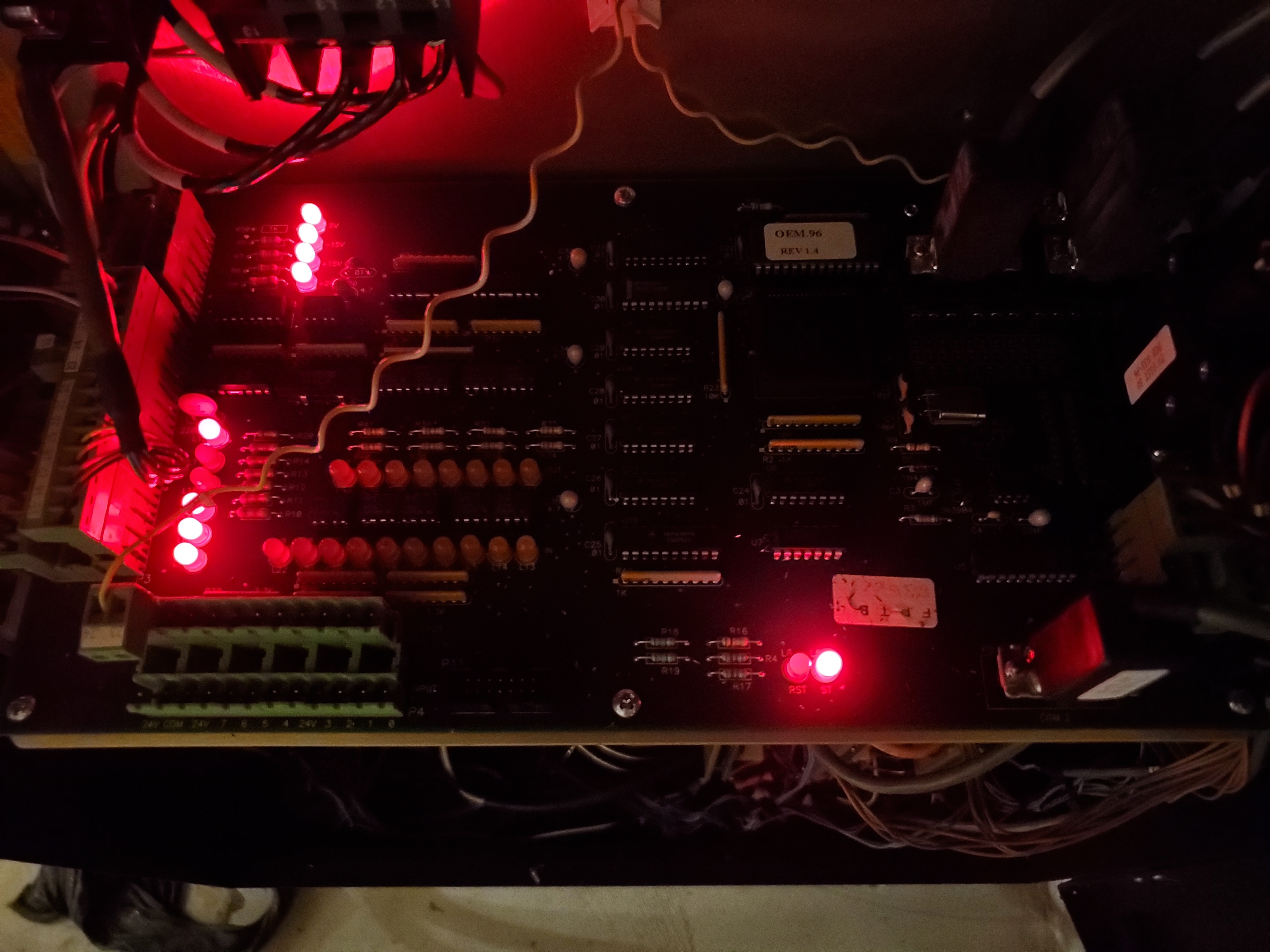
The S1100 Distribution board was a nicely laid out industrial board with the staple phoenix contact terminal blocks, connectors for each axis motor comms, optoisolators, Flip flops, demultiplexers, Darlington Switches, bus transceivers, bipolar buffers and an 8-bit microcontroller with A/D converter. Woah, but what's that? Those aren't PCB errors or soldermask imperfections. Those are metal chips! A thorough photographing, disassembly and cleaning is in order.
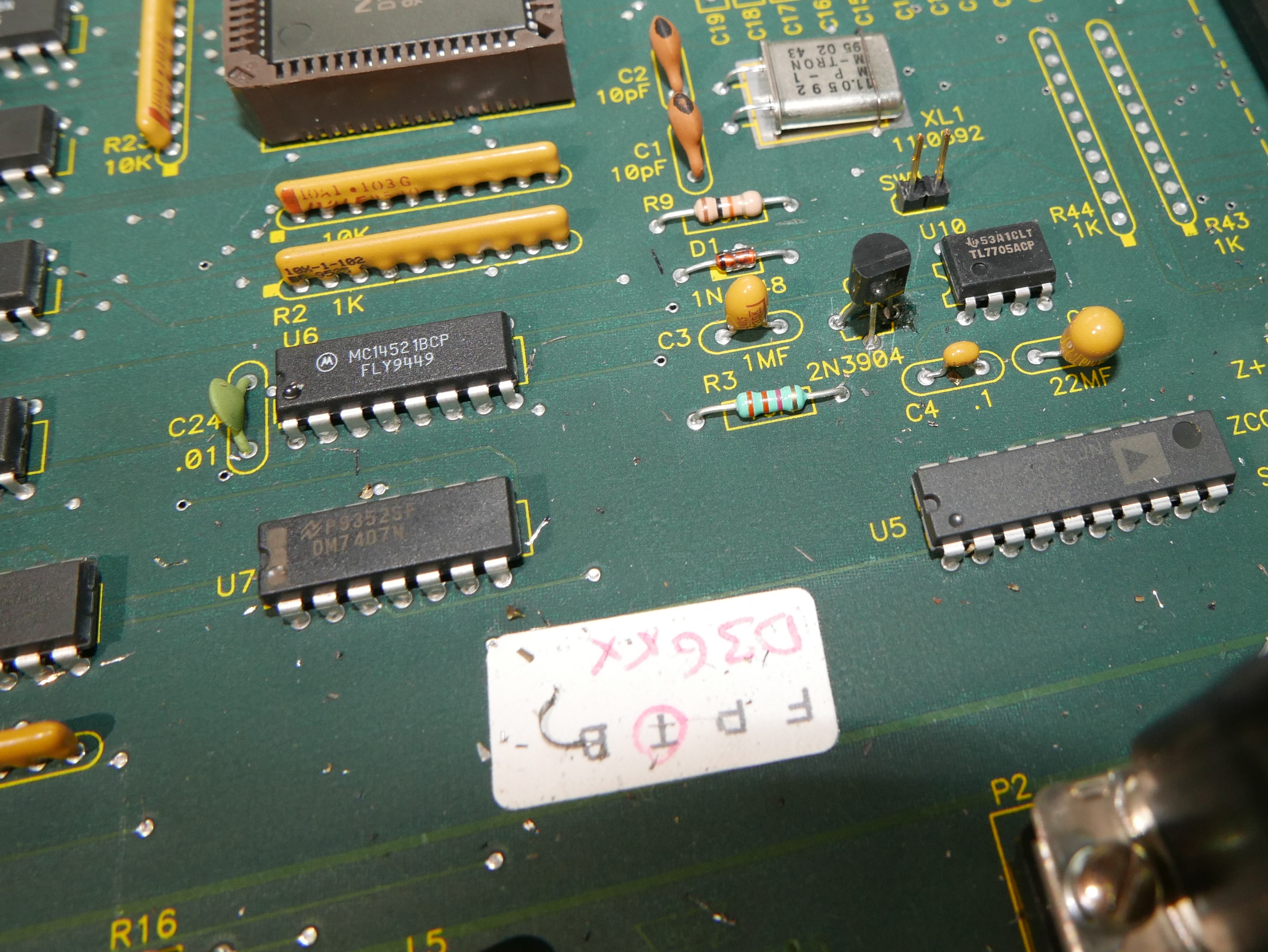
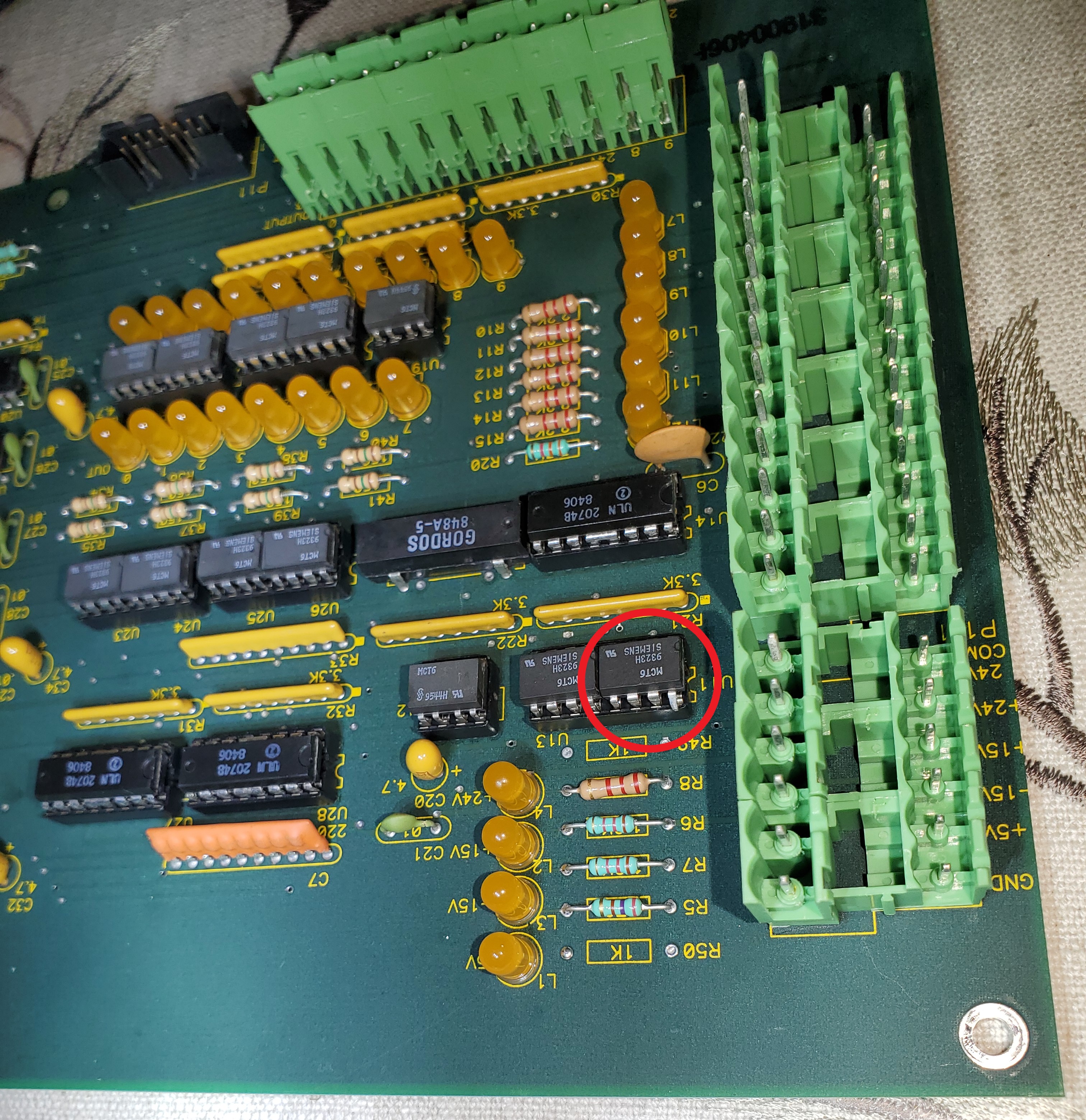
A cleaning with compressed air, brushing with IPA and optical inspection later, the Anilam S1100 finally looks presentable! The inspection was a true life-saver as one of the opto-isolators tried escaping. No way a floating leg would have passed QC checks...if there were QC checks? Shaggy would be proud. I grabbed some spare MCT6 optos from Digikey as a matter of course.
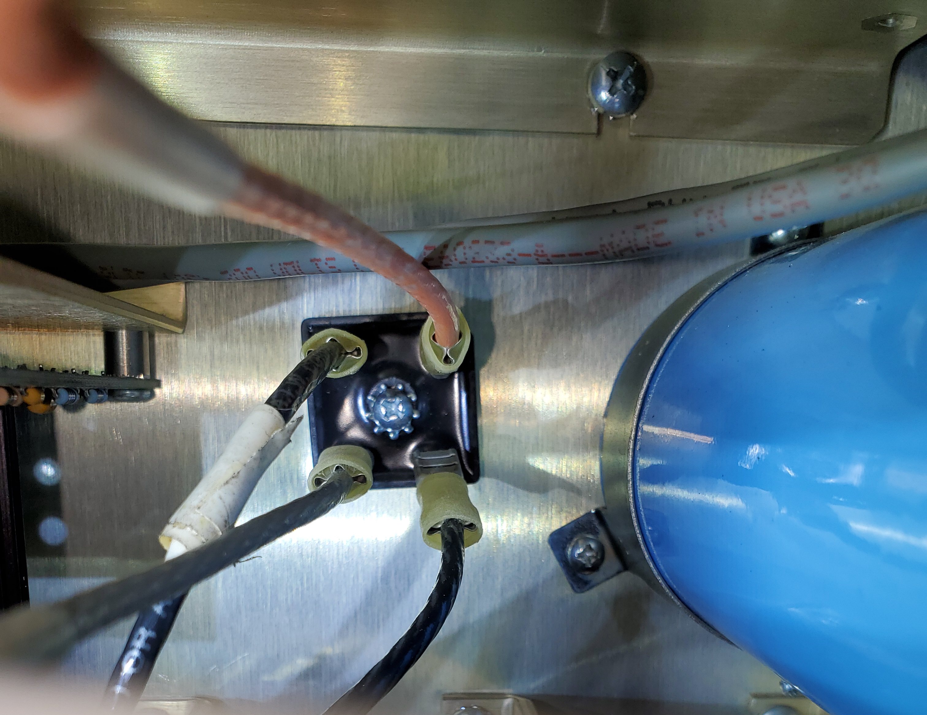
In terms of mechanical issues with the servo cabinet, the bottom most 40+ pin military-style circular had vibrated loose but none of the wires looked severed.
Reboot
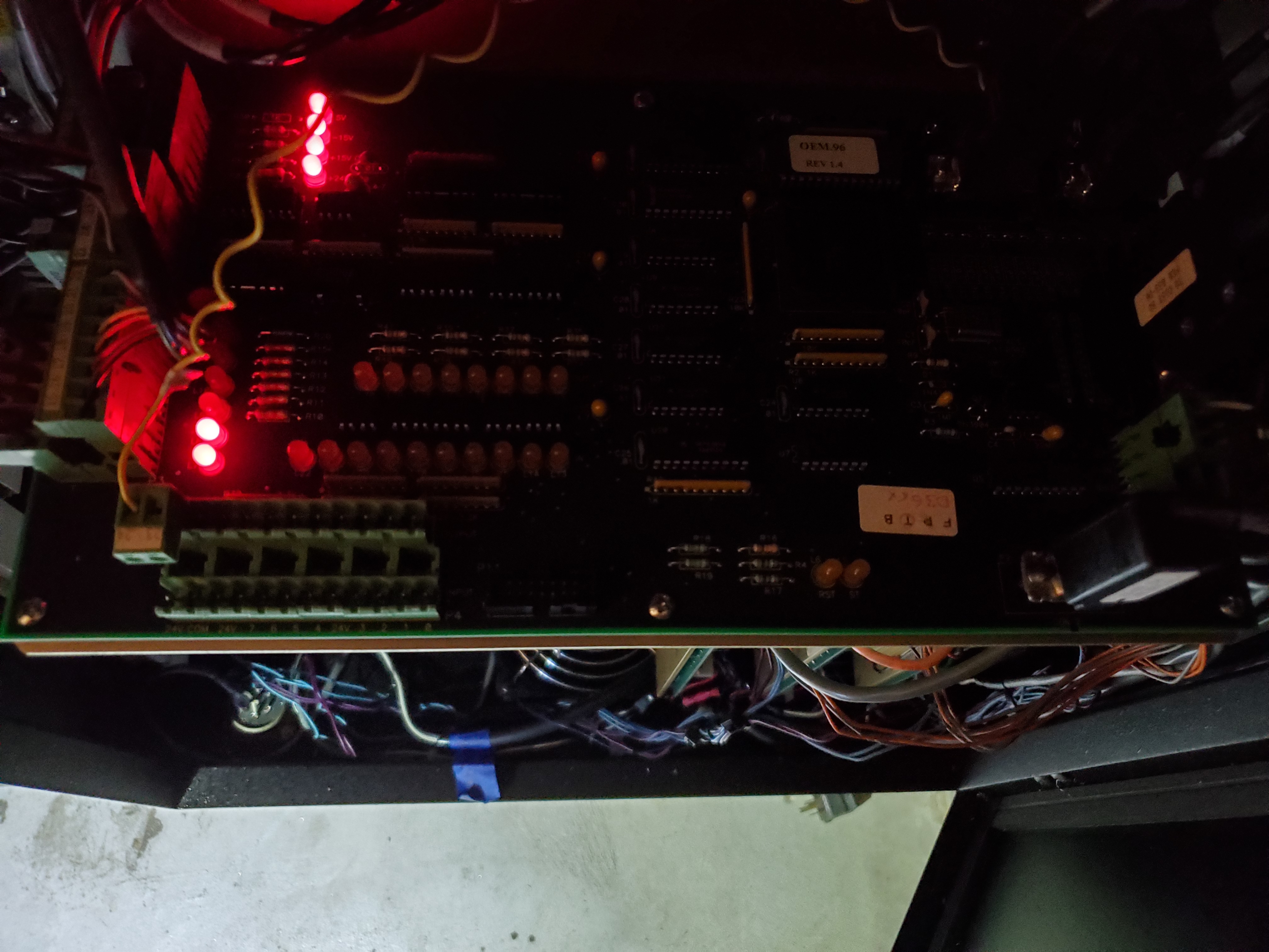
After discharging the mains cap and thoroughly vacuuming out the servo cabinet, I reinstalled the distribution PCB and rebooted the CNC. The machine definitely seemed a lot happier as the number of problematic diagnostic LEDs changed. However, the servo enable problems still lingered.


Luckily, the insanely helpful series 1100 troubleshooting guide listed a servo reset and servo enable circuit which helped to diagnose a failed 2N3904.
...check on the distribution board front left hand corner LED’s L7,L8,L9, and L12, must be illuminated. If any of these are out check the limit switch that corresponds to the LED. L7 usually is the X limit switch, L8 usually is the Y axis limit switch, and L9 usually is the Z axis limit switch. If X axis is the problem then all 4 LEDs will be off. However please check the 4 LEDs on the back left corner of the distribution board labeled L1,L2,L3, and L4, these must be illuminated!
—Ch2, Servo Won't Energize Series 1100 Troubleshooting Guide
Q1 was replaced and the troubleshooting continued. Between the replaced optoisolator and 2n3904, the servo errors vanished. Score for the books!
Axis Inspection
Time for axis check-in. The X-axis moved smoothly but would continue past its input positional location and cause faults on the machine. However, sometimes it operated perfectly fine. Inconsistency is not a desirable CNC characteristic. The Y-axis moved flawlessly and responded swiftly to control input. Z-axis did not phone home. No movement, no servo motor sounds, nothing. Just an error on the display.
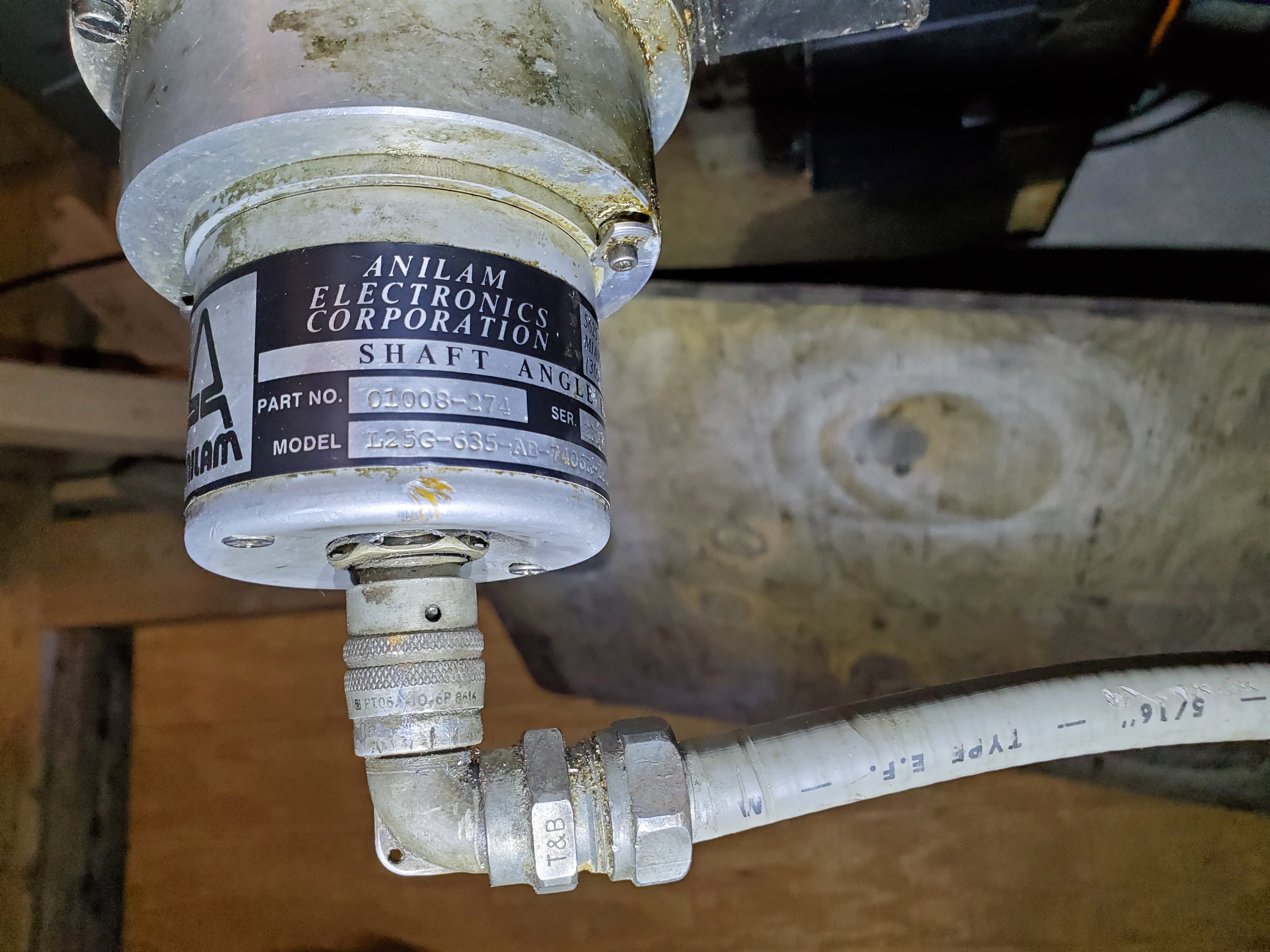
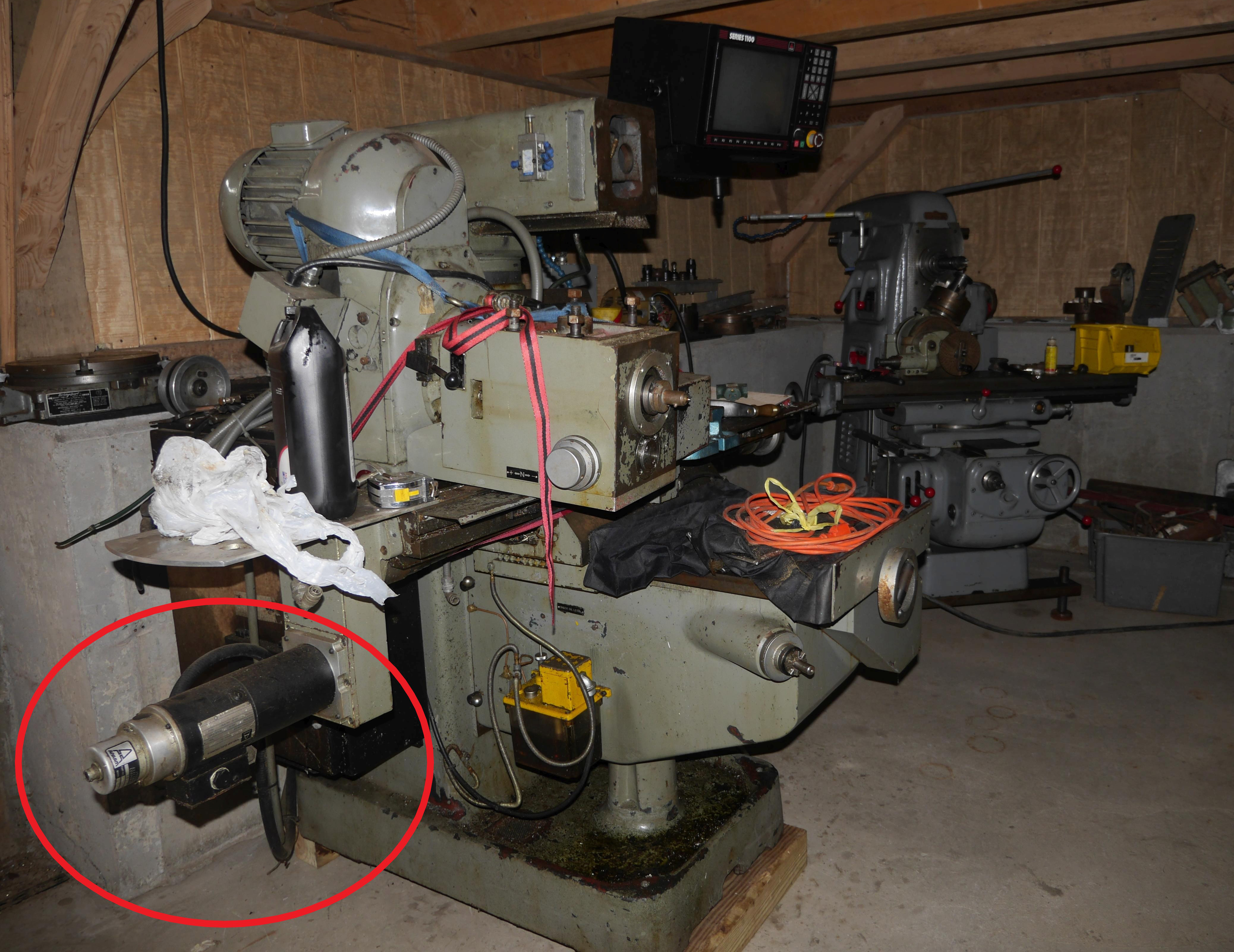
The X-axis problem was likely the damaged servo encoder as the military-style locking din connector was depressed into the sheet metal housing from being improperly moved. The entire connector assembly wobbles about. This is likely the "X-lag over max" culprit. However, we did not want to get carried away and checked the limit switches as well. Both tested out perfectly fine. The x-axis mount is a silly design, as the motor protrudes out from the frame by a good foot and a half. A right angle gearbox or a right angle servo cable connector is clearly a better solution. Luckily I found a replacement Anilam Encoder for a measly $40.49. It was a more desirable right-angle connector version with an incredibly close model number. I installed an Anilam L25G-625-
    shaft angle encoder
    part: 01008-274
    serial: K3044
    date: 10-30-86
    model: L25G-635-AB-7406R-EPT07 (609-113)
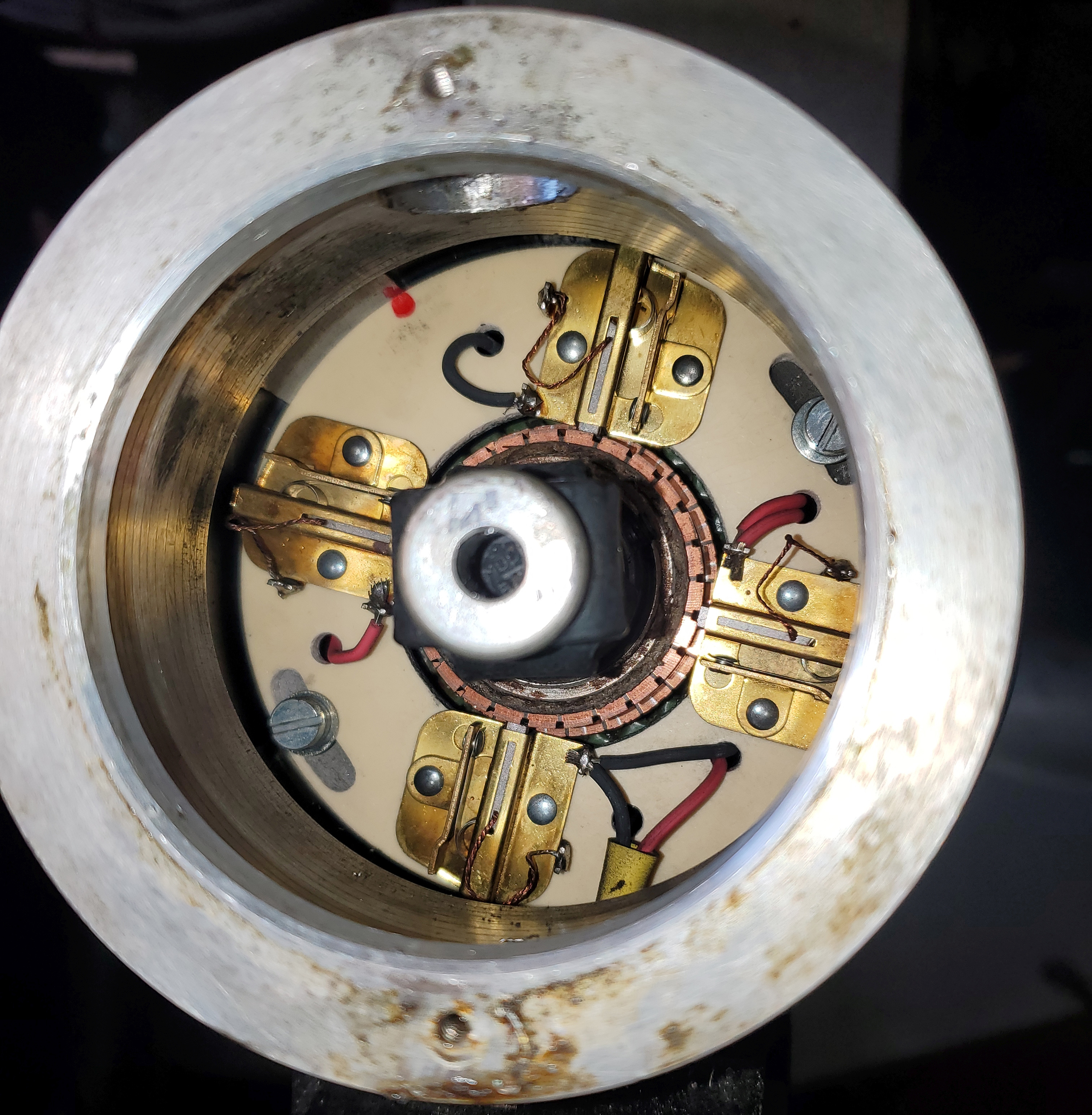
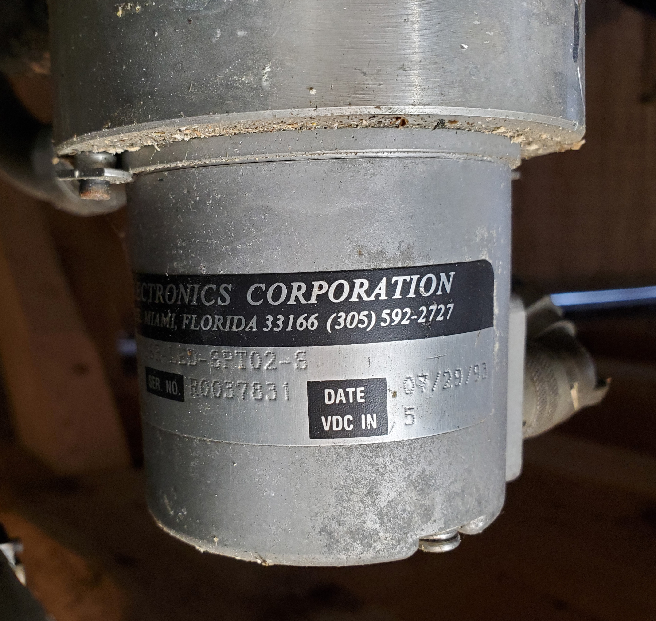
On installation, the encoder damage was more extensive than anticipated, with scoring on the inside of the encoder shell. It was certainly time for a replacement.
The Z-axis was more tiresome to troubleshoot. It seemed no matter the input, the Z-axis reading remained at 0.000. Nothing changed it, no matter what setting we adjusted or value input into the keypad. It was incredibly frustrating considering the effort taken to just get the machine installed and ready for operation. After a few days of sifting through the troubleshooting guides, illumination error codes, and programming manuals we decided to dig in.
This thing is a Dinosaur! You know what the problem is? Too many wires!!!
—Thomas Kouttron
We removed the front access cover to explore the Z-axis ball screw assembly. It turns out the Z-axis was simply outside of its travel limit. The entire ball nut assembly hit the limit switch and continued, forcing the roller against the ball nut body. The photo below does not perfectly show this, I may have taken it after we moved the ball nut assembly.
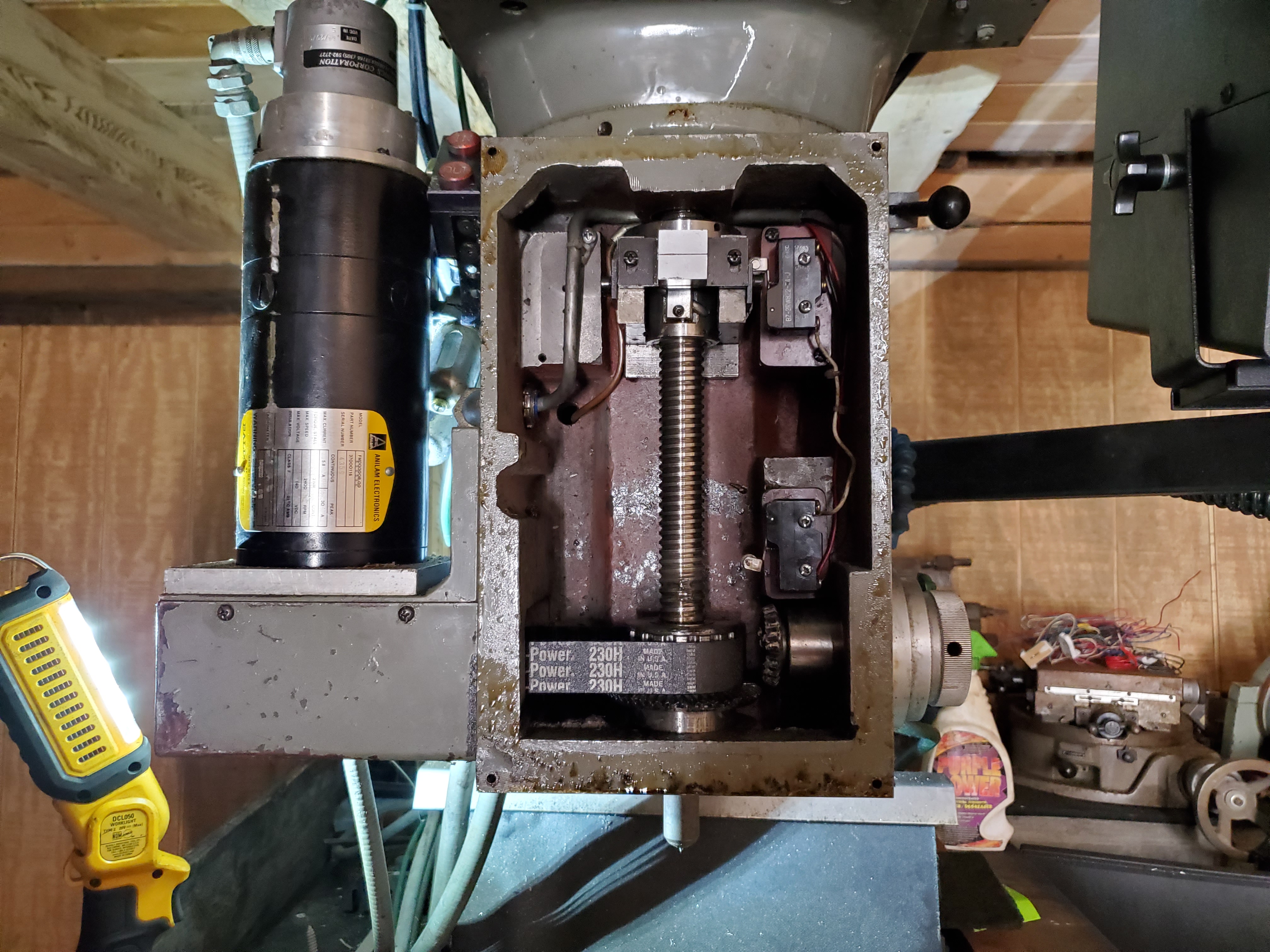
Thinking back, this issue may have also surfaced from improper shipping methods. Heavy machinery usually has provisions for movement during transport. I was unaware of any for this machine, but it is possible that there were locking pins or set screws for each axis to allow for proper fixture in transport. I bet the Z-axis ball nut simply vibrated upwards while the CNC was on the trailer and jammed the limit switch roller against the body, preventing easy motion.
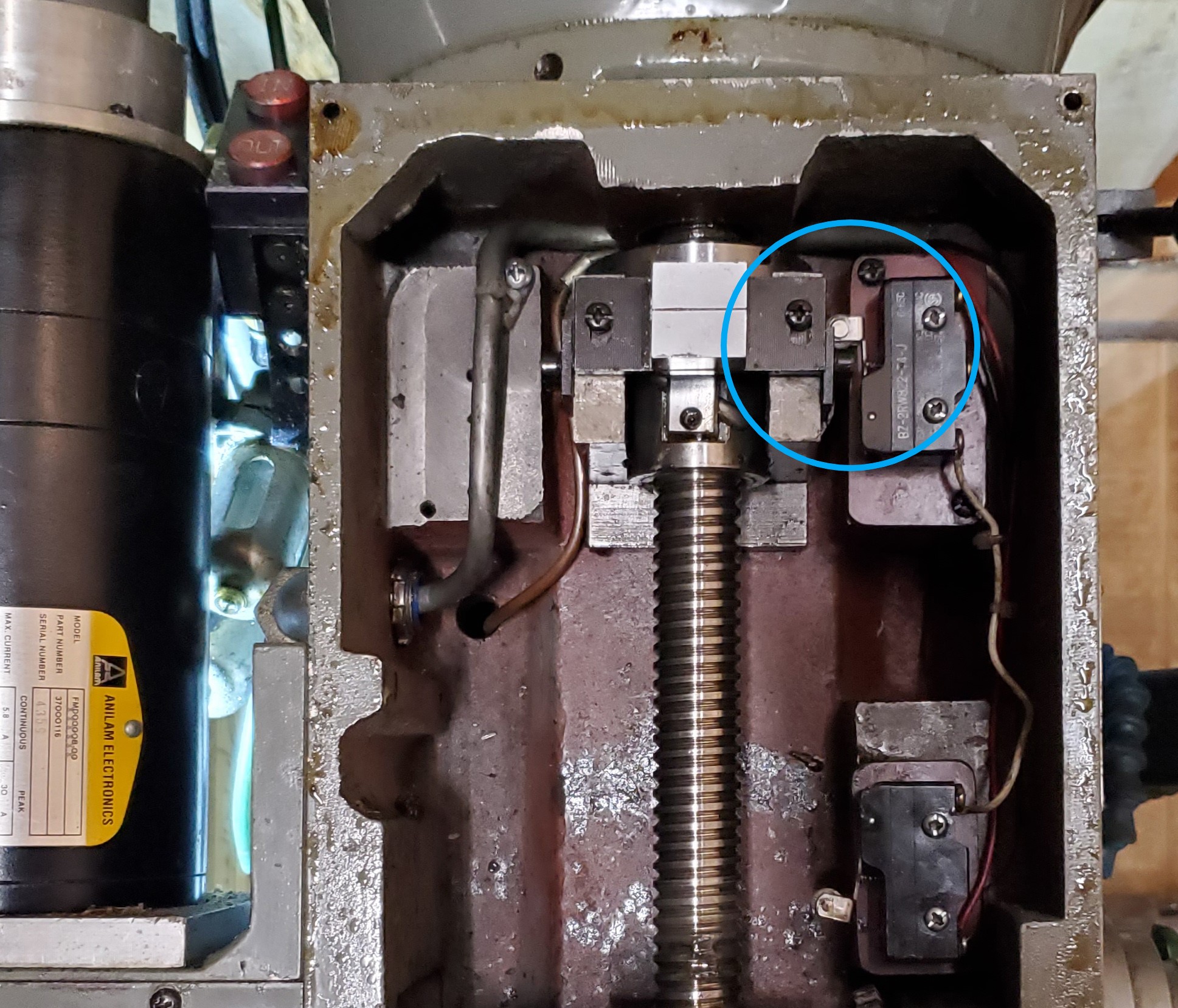

All we had to do was manually move the assembly down between the limit switches and we were able to control the spindle and spool up the spindle motor. We did not even have to calibrate the Z-axis either. Wild. Finally, we were able to fully communicate and control X, Y and Z axis.
Success
All axis were firing and ready to go! Now to just button up the machine and clean up. The video below only shows the Z and Y axis working properly as it was filmed before the X-axis servo swap.
Throwing Chips
As a means of celebration, the CNC was immediately put to work. Thomas is in the middle of restoring a very tired 1940s vintage Cletrac tractor. As you can imagine, parts are readily available at your local Sears and Roebuck :D. He has been doing some top notch engine stitching and machining to reintroduce the tractor to this century. While the CNC has an incredibly clunky interface, it's been invaluable to his restoration process, helping him recreate essential tractor parts.
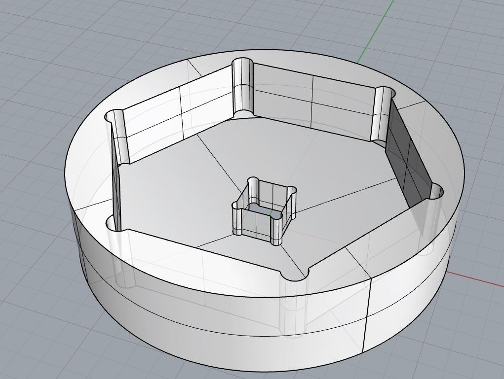
Another brother, Chris, needed a CNC to create a custom socket adapter tool for servicing Quincy air compressors. His Big-boy commercial-grade compressor needed some routine maintenance and the official Quincy tool used to torque down unloader towers is several hundred dollars. Not anymore!
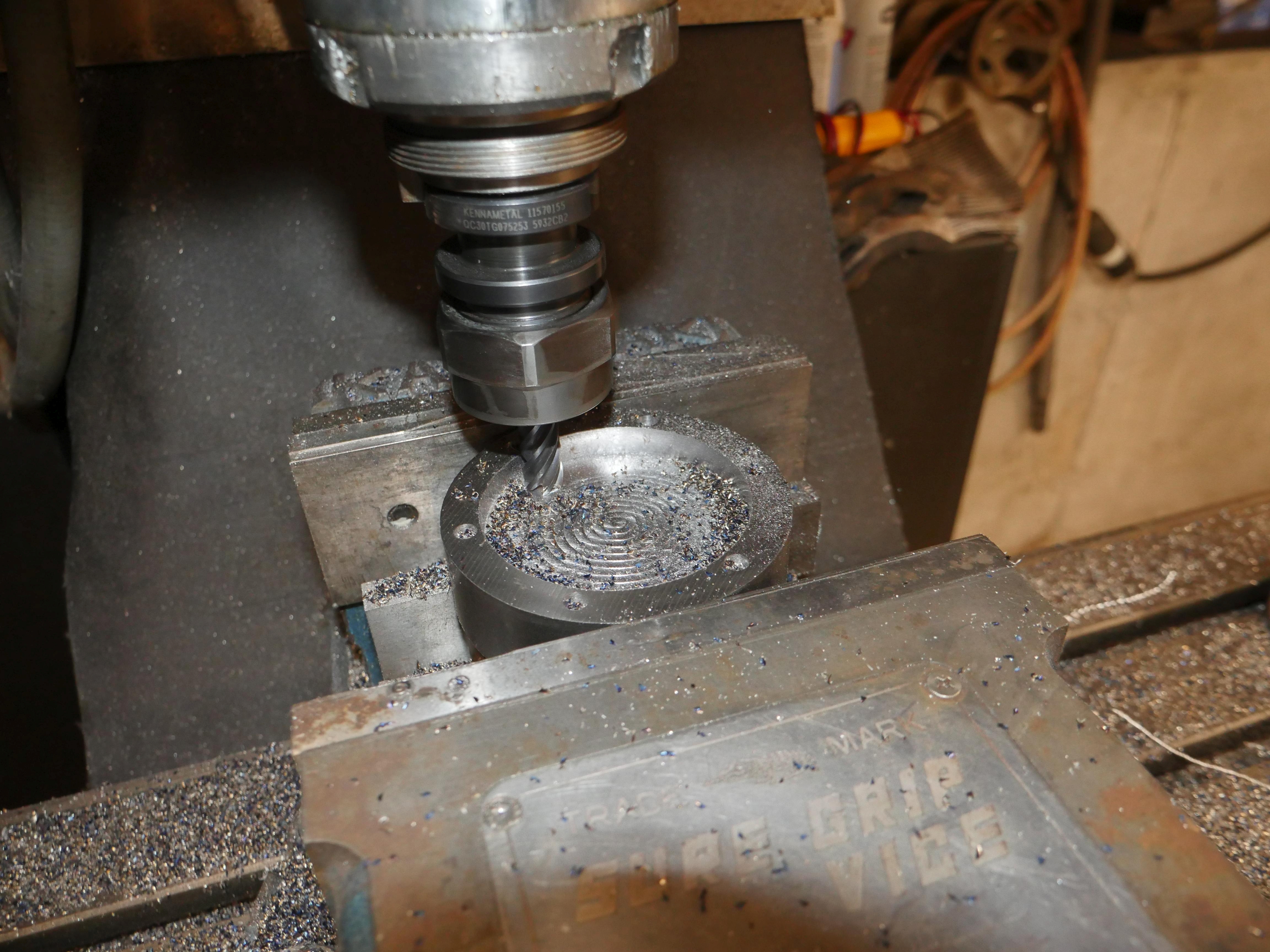
It certainly is mesmerizing to watch a machine actively do a task for you without your input. All the software folks out there, eat your heart out. This is what it's like to watch assembly code construct line by line on a terminal :D.
Future Upgrades
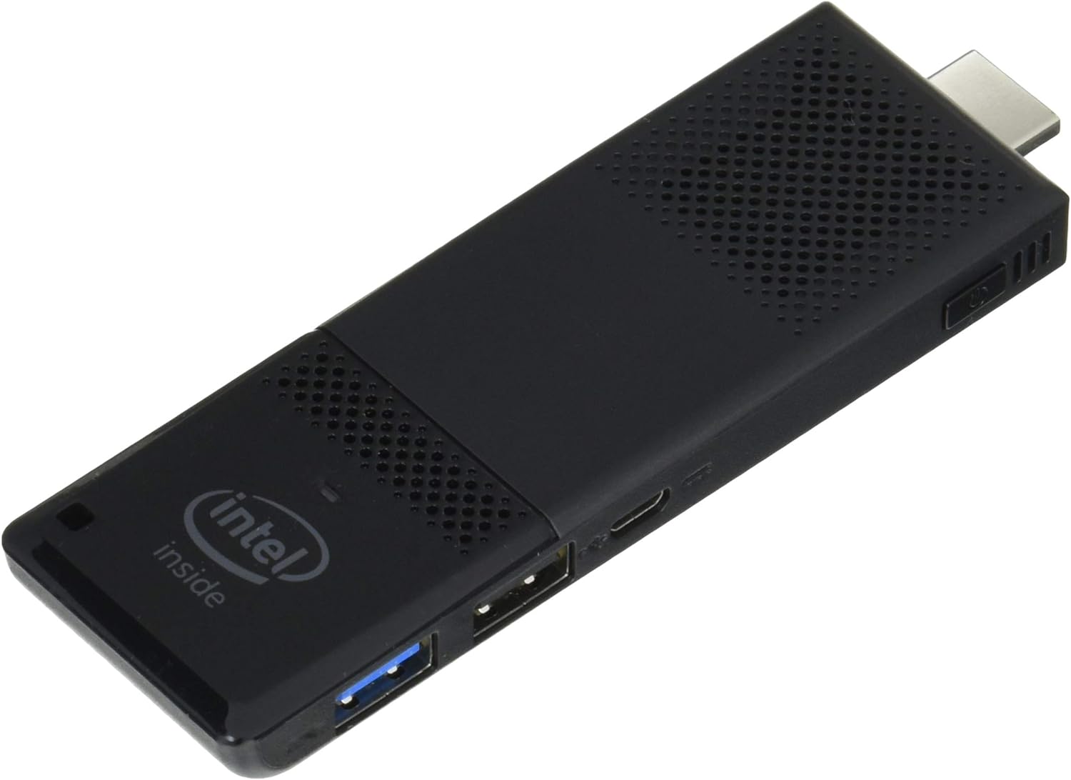
I think it's time this machine gets a true computational upgrade. A Raspberry Pi would blow that 486 out of the water, however it would need to run basic DOS. Boy does using DosBox to run CNC software sound like a bad idea. Maybe I'll get a Terasic DE10 Nano and run the entire thing on an Altera Cyclone V. An HDMI Intel compute stick would likely be the best bet and I could even tie it into a modern LCD. Oh the possibilities. For now I'll just grab a USB floppy emulator to make G-code import less painful.
Special Thanks
A huge thanks to my younger brother, Thomas Kouttron, for having the patience to wait a few months for the full machine diagnosis and repair. He could have easily called it quits, blamed the metric system, put the machine on marketplace and grabbed another CNC, but he didn't give up. That's a lot of staying power for someone who has always wanted a working CNC in his shop. Thomas you rock.

Thomas is the best
Thanks for Reading!
Want more? Here's a behind the scenes look at my workspace and some of the images that did not make the cut to be included in the write-up: